


Short answer: An underground pipe locator finds a buried metal pipe or cable by putting an alternating-current signal onto the line and then measuring the magnetic field that the current produces. The transmitter applies the signal by direct connection, clamp coupling, or induction. The current then sets up a magnetic field around the line, and the field gets weaker the farther you move from it. Coils in the receiver pick up that field. The point of strongest signal (peak) or weakest signal (null) marks the spot directly above the line. Depth comes either from a direct on-screen reading or from the 80% method. The TFN T6000 follows exactly this workflow, and the four steps below walk through it as you would do it on site.
Why Accurate Pipe Locating Matters
Striking a buried service is one of the most common and most expensive mistakes in excavation work. In the U.S., the Common Ground Alliance’s 2024 DIRT Report found that failure to notify 811 caused 24.54% of reported damages, and that excavators failing to maintain clearance after verifying marks caused 16.07% (CGA 2024 DIRT Report findings). The UK Health and Safety Executive’s guidance HSG47 makes the same point. It treats locating devices as a core part of safe digging, together with plans and safe excavation practice (HSE — Avoiding danger from underground services, HSG47).
A locator is only as good as the person using it. Knowing why the signal behaves the way it does helps you spot a bad reading before it turns into a damaged gas main.
How Does Electromagnetic Induction Locate a Buried Pipe?
All of electromagnetic pipe locating rests on two physical laws. A current creates a magnetic field, and a changing magnetic field induces a voltage.
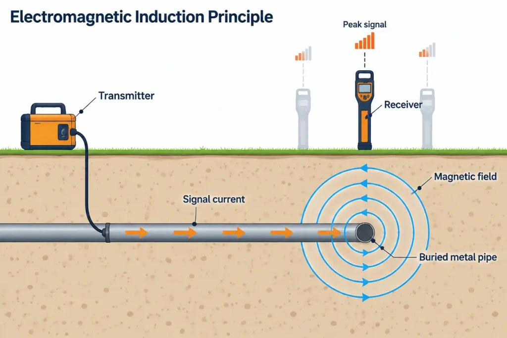
1. The transmitter puts an alternating current on the line
The transmitter generates an AC signal at a specific frequency and drives it onto the target conductor. It can do this in three ways:
| Method | How the signal reaches the line | Typical use |
|---|---|---|
| Direct connection | Clip leads attach to the de-energized conductor. Current flows out along the line and returns through the earth. | Strongest, cleanest signal. The first choice whenever you can safely access the line. |
| Clamp coupling | A clamp around a live cable induces the signal into it without breaking the circuit. | Energized cables that cannot be shut down. |
| Induction | A coil inside the transmitter radiates a primary field that induces current in buried conductors below it. No contact is needed. | Blind searches, lines with no access point, and shallow lines. |
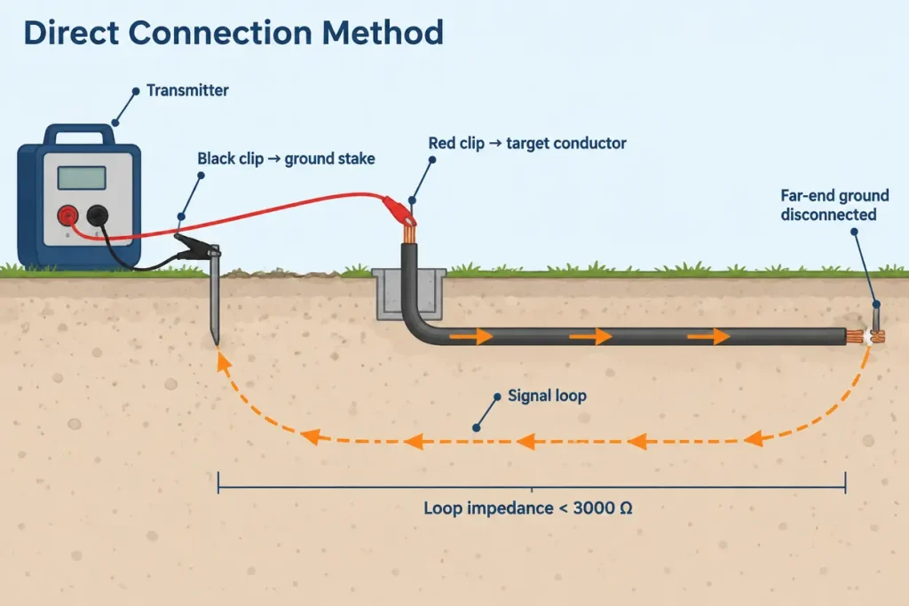
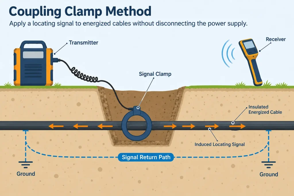
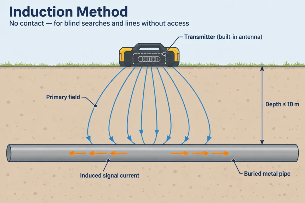
The signal needs a complete loop. With direct connection, current leaves on the target line and returns through the soil to the transmitter’s ground stake. This is why grounding quality and loop impedance have a direct effect on how much current actually reaches the line.
2. The current produces a magnetic field around the line
By Ampère’s law, current flowing in a long straight conductor produces circular magnetic field lines centered on the conductor. The field strength falls off roughly in proportion to 1/r, where r is the distance from the line. Directly above the pipe, the field lines run horizontally. Off to either side, they tilt more and more toward the vertical. This simple geometry is what makes it possible to find both position and depth.
3. The receiver turns the field back into a measurable signal
Because the current alternates, the magnetic field alternates too. By Faraday’s law of induction, a changing magnetic flux through a coil induces a voltage in that coil (Faraday’s law of induction; Electromagnetic induction). Each receiver coil responds only to the part of the field that runs along its axis. Coil orientation therefore determines what kind of response you see:
| Response | Coil orientation | Reading directly over the line | Strength | Weakness |
|---|---|---|---|---|
| Peak | Horizontal coil | Maximum signal, because the field is fully horizontal there | Stable and tolerant of field distortion | Broad response, so the exact center is less sharp |
| Null (trough) | Vertical coil | Minimum signal, because the field has no vertical component there | Very sharp position indicator | Shifts easily when nearby conductors distort the field |
On a clean, undistorted line, peak and null point to the same spot. If they disagree, the field is being distorted by a tee, a bend, or a neighboring conductor. That is a cue to slow down and investigate before you mark.
4. How depth can be read from the field
Field strength drops with distance, so a receiver with two horizontal coils stacked a known distance apart can calculate depth. It compares the signal at the lower coil with the signal at the upper coil, and the ratio between the two depends on how far the line is below the receiver. This principle is what makes instant on-screen depth readings possible. Like any field-based estimate, it assumes the receiver is centered over the line and the field is undistorted.
5. Why frequency choice matters
The frequency you pick changes how the signal behaves underground (A simple guide to cable and pipe locating methods):
| Frequency | Behavior | Best for |
|---|---|---|
| Lower | Travels farther along the line and bleeds less onto neighboring utilities | Long runs and congested corridors |
| Higher | Couples more easily into conductors, including through insulating joints and by clamp or induction, but bleeds onto nearby lines more | Coupling and induction modes, short or poorly connected lines |
The T6000’s 3-frequency synchronized output lets you match the signal to pipes of different materials and depths without changing equipment.
6. Separating the target from look-alike signals
At higher frequencies, some signal “bleeds” onto adjacent conductors. These lines carry return current flowing in the opposite direction to the current on your target. A receiver that measures current direction (signal phase) can tell the outgoing current on the target line apart from these return currents. This is exactly what the T6000’s current-direction function does in Step 2 below. The T6000 also uses anti-interference algorithms to reduce the effect of adjacent pipelines and environmental noise.
How to Locate a Metal Pipe With the TFN T6000 Locator: A 4-Step Workflow
Step 1: Apply the Signal (Transmitter)
- Direct connection (preferred): Connect the red clip to the phase conductor of the target cable. Connect the black clip to an independent ground stake. Disconnect the far-end ground wire so the signal forms a loop. Loop impedance must be below 3000 Ω.
- Coupling method (live work): Close the coupling clamp around the exposed cable. Select high frequency + high power to strengthen signal coupling.
- Induction method (blind search or shallow lines): Place the transmitter close to the ground. Its built-in antenna radiates a high-frequency signal into lines below it (depth ≤ 10 m).
The T6000 transmitter automatically detects impedance and optimizes signal strength, so you spend less time adjusting output by hand.
Step 2: Trace the Route (Receiver)
- Turn on the receiver, select Peak mode, and set the gain to the 60 dB baseline.
- Walk along the expected route and watch the signal strength bar and the digital value (00.0–99.9):
- Peak method: The point of maximum signal is directly above the line. The audio tone is at its fastest here.
- Null (trough) method: The point of minimum signal marks the center of the line. Use the on-screen arrows to confirm the route.
- Use the current-direction function (SS frequency):
- Forward current shows a “+” sign (phase −45° to 45°). Reverse current shows a “−” sign (phase −135° to 225°). This lets you rule out crosstalk signals from neighboring lines.
Step 3: Measure Burial Depth
- Direct reading (real-time display): Hold the receiver directly over the line with the compass pointing straight ahead. The screen shows depth (meters) and current (mA) in the upper-left corner.
-
80% method (complex environments):
- Record the signal value directly above the line (for example, 85.0).
- Calculate 80% of that value (85 × 0.8 = 68.0).
- Move sideways until the signal drops to 68.0. The distance between the two points is the burial depth.
Tip: If the direct reading and the 80% result differ significantly, the field is likely distorted. Re-check the peak/null agreement from Step 2 before you record a depth.
Step 4: Blind-Search for Unknown Lines (Induction Mode)
- Area sweep (surface method): Keep the transmitter and receiver 7 meters apart and move them slowly in parallel. Wherever the signal jumps, there is a line underneath. This works well for large-area surveys.
- Point search (radial method): Use the transmitter as the center point and walk the receiver around it on a 7-meter-radius circle. Connect the signal peak points to get the line’s direction. This works well for precise positioning.
Where Is the T6000 Used?
| Application | What the locator does |
|---|---|
| Municipal construction | Keeps excavation clear of water, gas, and power lines |
| Fault finding | Pinpoints cable short-circuit points and damaged sections |
| Pipe network mapping | Produces underground utility maps at ±5% of depth + 2.5 cm positioning accuracy |
| Emergency repair | Identifies buried lines fast to shorten repair time |
The T6000 locator‘s color compass navigation and audio intensity feedback also help reduce operator fatigue on long survey days.
Safety Checklist Before You Start
- Operators should be professionally trained and must strictly follow grounding procedures.
- Do not use the equipment in flammable or explosive environments.
- Charge lithium batteries only with the dedicated charger, and dispose of used batteries according to local environmental regulations.
- A locator is one layer of protection, not a guarantee. Combine it with utility records, an 811 or local one-call notification, and careful hand digging near marks, as HSG47 recommends.
FAQ
It puts an AC signal on the pipe. The pipe then radiates a magnetic field, and coils in the receiver detect it. The receiver shows a peak (maximum) or null (minimum) directly above the pipe.
Peak uses a horizontal coil and reads strongest directly over the line. It is stable but broad. Null uses a vertical coil and reads weakest over the line. It is sharper but more sensitive to distortion. When both point to the same spot, the reading is reliable.
Use direct connection whenever you can safely access a de-energized line, because it gives the strongest signal. Use clamp coupling for live cables. Use induction for blind searches or when there is no access point. On the T6000, induction works to a depth of about 10 m.
Lower frequencies travel farther and bleed less, so they suit long runs in congested areas. Higher frequencies couple better, so they suit clamp and induction modes. The T6000’s 3-frequency output lets you switch without changing equipment.