What is Bit Error Rate? In-depth Analysis and Precise Testing Methods
Bit Error Rate (BER) is a core metric for measuring the transmission reliability of digital communication systems. It directly reflects the probability of signal errors during transmission. The calculation formula is:
BER = Number of erroneously received bits / Total number of transmitted bits
For example, if 10 errors occur in a transmission of 1,000,000 bits, the BER = 10/1,000,000 = 10⁻⁵. A smaller BER indicates a system's stronger interference immunity and higher transmission quality.
Why is Bit Error Rate testing so important?
In communications engineering, BER is directly related to user experience and system stability:
Network Operation and Maintenance: Detecting attenuation and interference in physical links such as optical cables and coaxial cables
Equipment Acceptance: Verifying interface performance of devices such as routers and switches
Standards Compliance: Compliance with International Telecommunication Union (ITU) specifications such as G.821 and G.826
Fault Location: Quickly Identifying Transmission Anomalies Caused by Clock Skew and Signal Distortion
How to Accurately Test Bit Error Rate? TFN T1000M Bit Error Tester Practical Guide
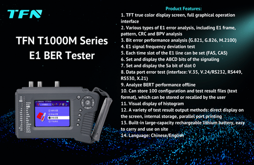
The TFN T1000M Handheld Bit Error Tester (refer to the upgraded TFN 2M Bit Error Tester) is a professional tool for field testing. Its operation process is as follows:

I. Test Principle: Transmission and Comparison
1. Transmitter:
The instrument generates a specific test pattern (such as a PRBS pseudo-random code (2E15-1, QRSS), etc.) and sends it to the device under test through an interface.
2. Transmission Link:
The signal passes through optical fibers, cables, or is processed internally by the device, potentially introducing interference such as noise and jitter.
3. Receiver:
The T1000M receives the signal, compares it bit by bit with the original pattern, counts the number of errors, and calculates the BER.
Key Settings: In the T1000M's [Parameter Settings], you can select:
Test Pattern: 32 patterns, including 511/2047/All 0s/All 1s (user-programmable custom patterns)
Interface Type: E1 (2.048Mbps), V.35, RS-232, etc.
Test Duration: 15 minutes to 24 hours of continuous testing
II. Detailed T1000M Operation Procedures
1. Physical Connection
Use a BNC cable (E1 unbalanced interface) or an RJ45 cable (E1 balanced interface) to connect to the device under test. For data service testing, connect a V.35/RS-530 cable or similar through the HD26 port.
2. Parameter Configuration
Main Menu → [E1 Test] or [Data Test]
Settings:
Framing Mode: PCM30/PCM31/Unframing
Clock Source: Internal/Recovered/External
Code Type: Select Standard PRBS or Custom
Time Slot: Supports individual testing of N x 64K channels (activated via [Time Slot Settings])
3. Execute the Test
Click [Start Test] and the T1000M will display the following in real time:
Error Count Interface: Bit Errors, Alarm Seconds
G.826 Analysis: Errored Seconds Rate (ESR), Severely Errored Seconds Rate (SESR)
Histogram: Visualizes the Time Distribution of Bit Errors (Scaled by Seconds/Minutes/Hours)
4. Save and Export Results
Connect to a PC via USB to export CSV reports.
Connect directly to a printer (supports automatic and scheduled printing upon error).
Engineering Application Case: Core Advantages of the T1000M
For example, during a carrier's SDH equipment acceptance test, engineers used the T1000M to complete the following:
1. Frequency Deviation Test: Detect E1 clock offset (adjustable to ±50ppm)
2. Stress Test: 24-hour BERT (Bit Error Rate) test with CRC-4 checksum
3. Fault Reproduction: Insert 10⁻⁶ forced bit errors to verify the device's alarm mechanism
4. Protocol Analysis: Decode Sa bits and CAS signaling using the [Overhead Test]
The test results successfully located an HDB3 encoding error caused by poor grounding (the "CODE ERR" LED displayed red), and the fault point with an excessive BER was quickly repaired.
T1000M Core Values:
True color Chinese interface, improving field operation efficiency by 50%
Supports both offline (out of service) and online (ongoing service) dual-mode testing
Stores 100 configurations, reusing ITU standard test templates
Built-in lithium battery, stable operation in high-temperature and high-humidity environments (0°C to 50°C)
Conclusion: BER testing is the "stethoscope" of communication quality
Bit error rate (BER) is like a "health indicator" for a communications system, and professional instruments like the TFN T1000M transform complex channel quality into visual data. Whether for 5G fronthaul link acceptance or Data Center Interconnect (DCI) operations and maintenance, accurate BER testing is the technical cornerstone for ensuring "error-free transmission." Understanding its principles and effectively utilizing the tools are core competencies for communications engineers.
