





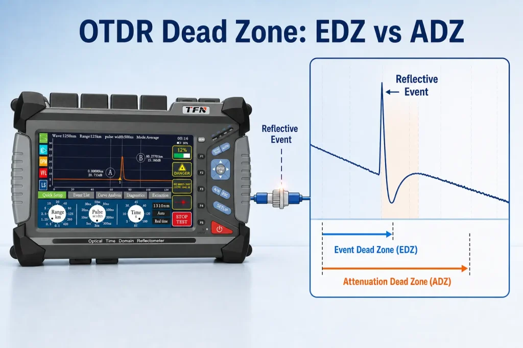
An OTDR dead zone is the length of fiber, immediately after a strong reflection, where the OTDR cannot detect or accurately measure events. It happens because the reflection temporarily saturates the OTDR’s detector — like being briefly blinded after a camera flash. There are two types: the event dead zone (can you see a second event?) and the attenuation dead zone (can you measure its loss?). A launch cable is the standard fix.
If a connector or splice falls inside a dead zone, the OTDR may hide it completely or report the wrong loss. For fiber contractors, this is one of the most common reasons a link “passes” on the OTDR but fails in the field — so it is worth understanding properly.
New to OTDRs entirely? Start with How Does an OTDR Work? for the underlying physics of reflections. This article assumes you know the basics and focuses on the dead zone problem.
What Causes a Dead Zone?
An OTDR works by sending out light pulses and measuring the faint light that scatters and reflects back (see How Does an OTDR Work?). Its detector is tuned to read that extremely weak backscatter.
When a strong Fresnel reflection hits — from a connector, a mechanical splice, or the OTDR’s own bulkhead — a huge spike of light returns all at once. That spike overwhelms the sensitive detector, which needs a brief moment to “recover” before it can read the faint backscatter again.
During that recovery period, the light is still traveling down the fiber. So the recovery time translates directly into a length of fiber that the OTDR effectively cannot see. That blind length is the dead zone.
Analogy: Walk out of a dark cinema into bright sunlight. For a few seconds you’re blinded and can’t see anything — then your eyes adjust. The OTDR’s detector does the same thing after a strong reflection. The distance the light travels during that “adjustment” is the dead zone.
The Two Types of Dead Zone
This is the distinction that trips up most technicians. There are two dead zones, and they measure two different things. Datasheets quote both.
Event Dead Zone (EDZ)
The event dead zone is the minimum distance after a reflective event at which the OTDR can detect a second, separate reflective event.
Think of it as the OTDR’s ability to tell two events apart. If two connectors are closer together than the EDZ, they merge into a single spike on the trace — you’ll see one event where there are actually two.
- What it limits: distinguishing closely spaced events (e.g. patch panels, short jumpers).
- Typical value: a good OTDR achieves an EDZ of around 1 meter at its shortest pulse width.
- What it does NOT give you: the ability to measure loss on those events.
Attenuation Dead Zone (ADZ)
The attenuation dead zone is the minimum distance after a reflective event at which the OTDR can accurately measure the loss of a subsequent event.
The ADZ is always longer than the EDZ. Detecting that something is there (EDZ) is easier than measuring it accurately (ADZ). The detector has to fully settle back onto the backscatter line before a loss reading is trustworthy.
- What it limits: accurate loss/insertion-loss measurement near an event.
- Typical value: around 4 meters at short pulse width on a good OTDR.
- Why it matters most for acceptance testing: if a connector falls inside the ADZ of a previous event, its measured loss is unreliable — even if you can see it.
| Event Dead Zone (EDZ) | Attenuation Dead Zone (ADZ) | |
|---|---|---|
| Answers the question | Can I see two events separately? | Can I measure the loss accurately? |
| Relative length | Shorter | Longer (typically ~3–4x EDZ) |
| Typical value (short pulse) | ~1 m | ~4 m |
| Main impact | Merged / hidden events | Wrong loss readings |
| Critical for | Counting events | Acceptance / certification testing |
How Pulse Width Makes It Worse
Here is the trade-off that connects the dead zone to the rest of OTDR testing: the wider the pulse width, the larger the dead zone.
A longer pulse puts more energy into the fiber, which means it reaches farther and reads longer links — but it also means the detector is hit with a bigger, longer reflection and takes longer to recover. So:
- Short pulse width → small dead zones, high resolution, but short range and more noise.
- Long pulse width → large dead zones, low resolution near events, but long range and cleaner distant readings.
This is why you cannot test a short data-center link and a long-haul outside-plant span with the same settings. It’s also why “auto” mode sometimes hides an event that a manual short-pulse scan would reveal. We cover how to choose settings in How to Use an OTDR Step-by-Step.
Why Dead Zones Cost Contractors Money
Dead zones are not an academic curiosity — they cause real, expensive field problems:
- The first connector is invisible. Every OTDR has a reflective event at its own front panel (the launch connector). The dead zone from that event falls right at the start of your fiber — exactly where your first connector usually is. Without a fix, you cannot measure your first connector at all.
- Merged events hide faults. Two closely spaced splices reading as one can mask a bad splice hiding behind a good one.
- False “pass” results. A connector inside the ADZ may report artificially low loss, so a marginal link passes certification — then fails when traffic goes live.
- Disputed acceptance. If your OTDR can’t measure the first and last connectors, the customer’s acceptance test (with a launch and receive cable) may disagree with yours.
How to Reduce or Eliminate Dead Zones
You cannot eliminate the physics, but you can move the dead zone off the part of the link you care about. Four practical methods:
1. Use a Launch Cable (the standard fix)
A launch cable (also called a launch fiber, pulse suppressor, or fiber ring) is a spool of fiber — typically 100–500 m or more — connected between the OTDR and the fiber under test.
It works by moving the OTDR’s own front-panel dead zone into the launch cable instead of your link. By the time the pulse reaches your first real connector, the detector has fully recovered and can measure it accurately. A receive cable at the far end does the same for your last connector.
This is the single most important accessory for accurate OTDR testing. We cover selection and length in OTDR Launch Cable: What It Is and How to Choose One.
2. Use the Shortest Practical Pulse Width
For short links or events close together, drop to the shortest pulse width your range allows. This minimizes both dead zones — at the cost of range, so only use it when the link is short enough.
3. Keep Connectors Clean
A dirty or damaged connector produces a stronger, messier reflection, which enlarges the dead zone. Inspecting and cleaning every connector endface before testing keeps reflections — and dead zones — as small as possible.
4. Check the Datasheet Before You Buy
Dead zone specs are a primary quality differentiator between OTDRs. When comparing instruments, always check the EDZ and ADZ at the shortest pulse width, and confirm at which pulse width those numbers are quoted (vendors sometimes quote best-case values). Smaller is better.
How to Spot a Dead Zone on the Trace
On a real trace, a dead zone looks like this:
- A reflective spike shoots up (the event).
- Immediately after the peak, the line does not return cleanly to the backscatter slope — it stays elevated and gradually settles.
- The horizontal distance from the spike until the line rejoins the normal slope is roughly the dead zone.
Any event that falls inside that recovering region is either invisible (inside EDZ) or unmeasurable (inside ADZ). Learning to recognize this pattern is part of trace reading, covered in How to Read an OTDR Trace.
Preguntas frecuentes
The event dead zone (EDZ) is the minimum distance needed to detect two separate reflective events. The attenuation dead zone (ADZ) is the longer distance needed to accurately measure the loss of an event. EDZ is about seeing; ADZ is about measuring.
On a good OTDR at its shortest pulse width, the event dead zone is around 1 meter and the attenuation dead zone around 4 meters. Both grow larger as pulse width increases.
A launch cable moves the OTDR’s own front-panel reflection and its dead zone into a spool of fiber before your link. By the time the pulse reaches your first connector, the detector has recovered, so that connector can be measured accurately.
Yes. If a connector falls inside the attenuation dead zone of a previous event, its measured loss can be artificially low, letting a marginal link pass certification and then fail in service.
Resumen
An OTDR dead zone is the stretch of fiber right after a strong reflection where the detector is temporarily blinded. It comes in two forms: the event dead zone (the minimum distance to detect two separate events, ~1 m) and the attenuation dead zone (the longer distance needed to accurately measure loss, ~4 m). Wider pulse widths enlarge both. Because the OTDR’s own launch connector creates a dead zone at the very start of your link, a launch cable is the standard solution — moving the blind spot off your fiber so your first and last connectors can be measured accurately. Understanding dead zones is what separates a technician who trusts the trace blindly from one who knows when the trace is lying.