




An OTDR works by launching short pulses of laser light into one end of a fiber, then measuring the tiny fraction of light that scatters and reflects back to the same end. Because light travels through glass at a known, constant speed, the OTDR converts the return time of each signal into a precise distance — building a full map of the fiber link from a single end.
That is the entire principle in one sentence. The rest of this article explains how each part actually happens — and why it matters when you are reading a real trace on site.
If you only need the plain-English definition of what an OTDR is, start with What Is an OTDR? A Plain-English Introduction. This article goes one level deeper into the physics.
The Core Idea: Radar for Fiber
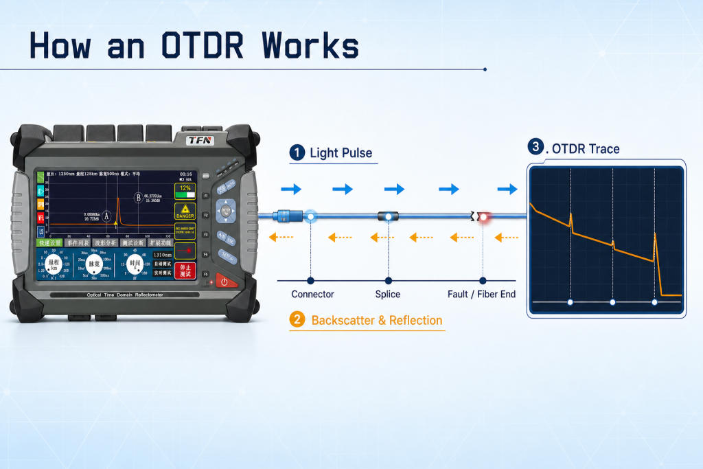
An OTDR (Optical Time Domain Reflectometer) uses the same fundamental principle as radar and sonar — send out a signal, listen for the echo, and use the round-trip time to calculate distance. The difference is the signal: instead of radio waves or sound, an OTDR uses pulses of laser light traveling through a glass fiber.
Here is the four-step cycle that repeats thousands of times during a single test:
- Emit — A laser diode fires a short, high-power pulse of light into the fiber.
- Travel — The pulse moves down the fiber at roughly two-thirds the speed of light in a vacuum.
- Return — A small amount of light continuously scatters and reflects back toward the OTDR along the way.
- Measure — A sensitive photodetector records the strength and arrival time of the returning light.
The OTDR repeats this cycle many times, averages the results to reduce noise, and plots them as a single curve called the trace.
Why Light Comes Back: Two Different Mechanisms
The light returning to the OTDR is not one signal — it comes from two distinct physical effects. Understanding the difference is the key to reading any trace correctly.
1. Rayleigh Scattering (the sloping backbone of the trace)
As light travels through the glass core, it interacts with microscopic density variations frozen into the fiber during manufacturing. This causes a small, continuous fraction of the light to scatter in all directions — including straight back toward the source. This is called Rayleigh backscatter.
Rayleigh scattering happens along the entire length of the fiber, not at a single point. On the trace, it appears as the gently descending diagonal line: the further the light travels, the more it attenuates, so less scatter returns from far away. The slope of that line is the fiber’s attenuation rate (measured in dB/km).
2. Fresnel Reflection (the spikes on the trace)
Whenever light hits an abrupt change in the material it is traveling through — specifically a change in the refractive index — a portion of it reflects straight back like a mirror. This is called Fresnel reflection, and it is far stronger than Rayleigh backscatter.
Fresnel reflections happen at specific points:
- Connectors (glass-to-air-to-glass gaps)
- Mechanical splices
- Fiber breaks
- The far end of the fiber
On the trace, these appear as sharp upward spikes. This is why a connector shows both a loss (a step down) and a reflective peak, while a good fusion splice — which has almost no refractive-index change — shows a loss with little or no spike.
The key distinction: Rayleigh scattering is continuous and tells you about the fiber itself. Fresnel reflection is localized and tells you about events — connectors, splices, and faults.
From Return Time to Distance
The “Time Domain” in OTDR is where the distance measurement comes from. The instrument records exactly how long each returning signal takes to arrive after a pulse is launched.
Light travels through single-mode fiber at approximately 204,190 km/s — about 68% of its speed in a vacuum. This ratio is governed by the fiber’s Group Index of Refraction (IOR), typically around 1.4682 for standard single-mode fiber.
The OTDR calculates distance with this relationship:
Distance=2×nc×t
Where:
- c = speed of light in a vacuum
- t = round-trip time of the returning signal
- n = group index of refraction (IOR) of the fiber
- The factor of 2 accounts for the round trip (out and back)
This is why setting the correct IOR matters. If the IOR value in your OTDR does not match the actual fiber, every distance reading will be off. A wrong IOR is one of the most common causes of “the fault is not where the OTDR said it was.”
The Settings That Shape Every Measurement
An OTDR does not have one fixed way of testing. The operator (or the auto mode) chooses settings that trade off range, resolution, and accuracy. Three settings matter most.
Pulse Width — the resolution vs. range trade-off
The pulse width is how long the laser stays on for each pulse. It creates a direct trade-off:
| Ancho de pulso óptico | Effect | Best For |
|---|---|---|
| Short (e.g. 3–30 ns) | High resolution, sees closely spaced events, but weak signal / short range | Short links, data centers, events close together |
| Long (e.g. 1–20 µs) | Strong signal, long range, but poor resolution and larger dead zones | Long-haul, outside plant, distant faults |
There is no universally “correct” pulse width — it depends on the link you are testing. This is also the root cause of the dead zone, an area right after a strong reflection where the OTDR is temporarily blinded and cannot resolve events. Because the dead zone is such a common source of confusion, we cover it in depth in OTDR Dead Zone Explained.
Range
The distance setting must be longer than the fiber under test. Setting it too short truncates the trace; setting it far too long wastes resolution.
Averaging Time
Because backscatter is so faint, the OTDR sends thousands of pulses and averages the returns to lift the real signal out of background noise. Longer averaging produces a cleaner trace and better dynamic range, but takes more time per test. A quick 15-second scan and a 3-minute averaged scan of the same fiber can reveal different levels of detail.
Single-Mode vs. Multimode: Wavelength Changes the Physics
The wavelength of the test pulse must match the fiber type, because attenuation and scattering behave differently at different wavelengths.
| Tipo de fibra | Typical OTDR Wavelengths | Why |
|---|---|---|
| Single-mode (SMF) | 1310 nm and 1550 nm | Standard for telecom, FTTH, long-haul. 1550 nm shows lower loss and reveals bends. |
| Multimode (MMF) | 850 nm and 1300 nm | Standard for data centers and short building runs. |
Rayleigh scattering is wavelength-dependent — it decreases as wavelength increases. That is why the same fiber tested at 1550 nm shows lower attenuation than at 1310 nm, and why testing at two wavelengths can reveal problems (like macrobends) that only appear at the longer wavelength. Choosing the right wavelength is a decision in itself, covered in the pillar guide.
Putting It All Together: How the Trace Is Built
When you combine all of the above, the trace makes sense as a physical story read left to right:
- The starting spike — Fresnel reflection from the OTDR’s own connector / launch point.
- The descending diagonal line — continuous Rayleigh backscatter; its slope is the fiber’s dB/km loss.
- A small step down with no spike — a fusion splice (loss, minimal reflection).
- A step down with a spike — a connector or mechanical splice (loss + reflection).
- A sudden spike then a drop to the noise floor — the end of the fiber, or a break.
Learning to interpret each of these features in detail — including tricky cases like “gainers” where a splice appears to add signal — is a skill of its own. We walk through it event by event in How to Read an OTDR Trace.
Preguntas frecuentes
Because it measures light that returns to the source via backscatter and reflection, rather than light that exits the far end. This is its biggest practical advantage over an optical power meter, which needs a source at one end and a meter at the other.
Backscatter (Rayleigh scattering) is continuous along the whole fiber and forms the sloping line that shows attenuation. Reflection (Fresnel reflection) happens at specific points like connectors and breaks, appearing as sharp spikes.
The fiber attenuates light as it travels, so backscatter returning from farther away is weaker. The steeper the slope, the higher the fiber’s loss per kilometer.
Yes. Short pulses give better resolution but shorter range; long pulses reach farther but create larger dead zones and blur closely spaced events. Matching pulse width to the link is essential for accurate results.
The most common cause is an incorrect Index of Refraction (IOR) setting. Since the OTDR converts time to distance using the fiber’s IOR, a mismatched value shifts every distance reading. Confirm the IOR specified by your fiber manufacturer.
Resumen
An OTDR works by turning light into a ruler. It launches laser pulses, listens for two kinds of returning light — continuous Rayleigh backscatter (which reveals the fiber’s attenuation) and localized Fresnel reflections (which reveal connectors, splices, and faults) — and converts the return time of each signal into distance using the fiber’s index of refraction. The pulse width, range, averaging, and wavelength settings all shape what the resulting trace can show. Once you understand these mechanics, the trace stops being a mysterious wavy line and becomes a readable map of the entire fiber link.