


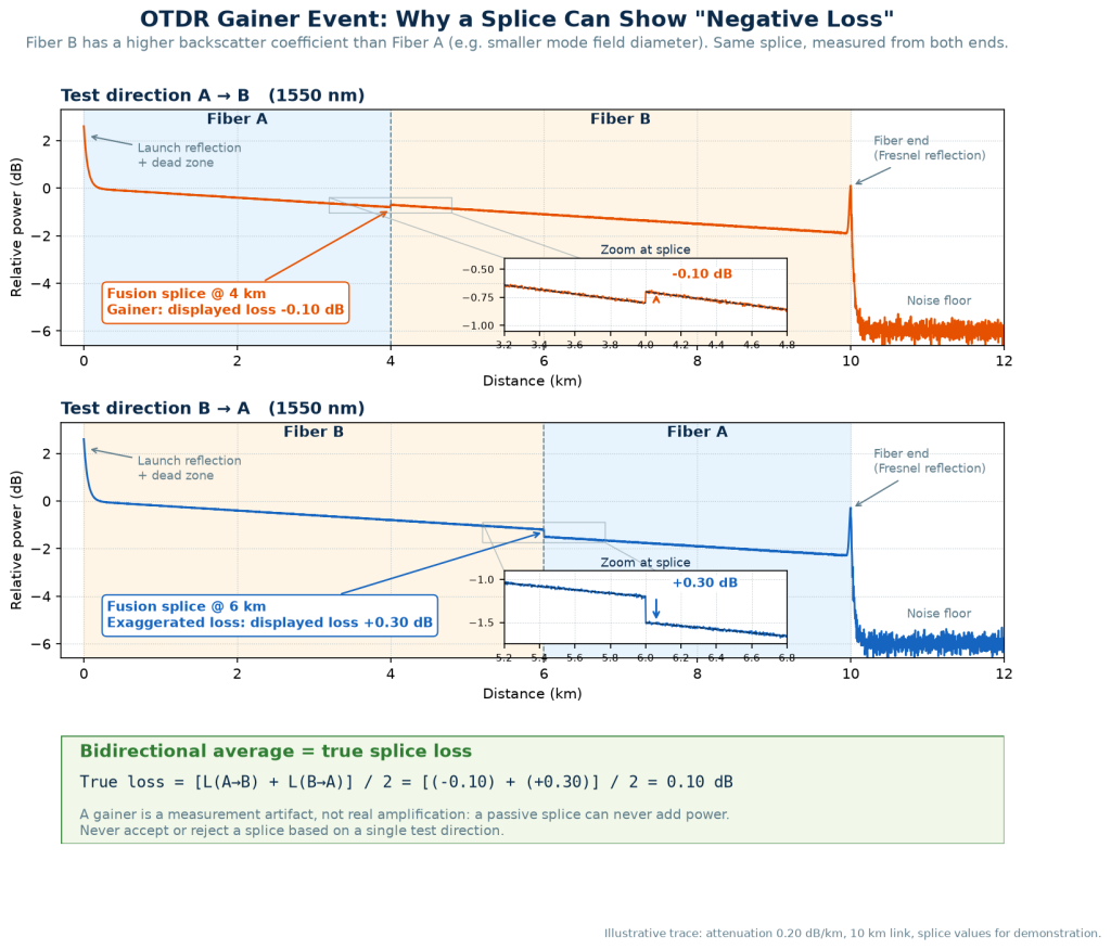
A gainer is a splice or connector that an OTDR shows with negative loss, as if the joint added light to the fiber. It can’t. A passive splice always loses some power. The “gain” happens because the fiber after the splice scatters more light back to the OTDR than the fiber before it, and the OTDR reads the higher backscatter level as a step up.
So a gainer is a measurement artifact, not a property of the splice. The real splice loss is hidden inside it, and you only get that number back by testing from the other end and averaging.
What a Gainer Looks Like on the Trace
On a normal fusion splice, the trace steps down a little and continues at the same slope. On a gainer, the trace steps up instead, and the event table shows a negative value such as -0.04 dB or -0.12 dB.
Two details usually give it away:
- The slope changes at the event. The fiber after the splice often has a different attenuation slope from the fiber before it. That is a hint the two fibers are not the same, which is the root cause.
- There is no reflective spike. A fusion splice gainer is a clean step up. If you see a spike followed by a “gain”, look at the other causes later in this article first.
Some OTDRs label these events “gain” or flag them in a different color. Others just print the negative number and leave the interpretation to you.
Why It Happens
An OTDR doesn’t measure splice loss directly. It compares the backscatter level just before the event with the level just after it, and calls the difference loss. That only works when both fibers send back the same fraction of light.
They often don’t. Two things change how much light a fiber scatters back toward the OTDR:
- Backscatter coefficient. Differences in glass composition and core design change how strongly the fiber scatters.
- Mode field diameter (MFD). A smaller mode field captures a larger share of the scattered light and guides it back, so the trace sits higher.
If the second fiber returns more light than the first, the jump in backscatter can be larger than the real splice loss. The OTDR sees the level rise, and you get a gainer.
Shoot the same splice from the other end and the effect flips. The fiber with less backscatter is now on the far side, so the OTDR adds the backscatter difference to the real loss. That direction shows a “loser”: a splice that reads much worse than it is. The Fiber Optic Association makes the same point in its OTDR reference page: the splice loss is the same in both directions, and only the OTDR’s view of it changes.
Where You’ll Run Into Gainers
Gainers aren’t random. They show up wherever two different fibers meet:
- Cable from different manufacturers spliced together, which is common on long routes built in phases or repaired with whatever cable was in stock
- Different fiber types joined in the same link, for example standard single-mode spliced to a bend-insensitive or dispersion-shifted fiber
- Repair sections, where a short piece of replacement cable is spliced into an older route
- Pigtails in splice closures and ODFs, where the pigtail fiber isn’t the same type as the trunk cable
A useful pattern: when a short section of higher-backscatter fiber is spliced into a link, the first splice shows a gain and the second shows an unusually high loss. The two errors roughly cancel. If you see a gainer followed shortly by a “bad” splice, check the cable records before you send someone to re-splice.
The size of the effect can also change with wavelength, so a splice can be a gainer at one wavelength and a small loss at the other. That alone doesn’t mean anything is wrong.
A Gainer Doesn’t Mean the Splice Is Good
This is the mistake that costs money. A technician sees -0.03 dB, assumes the splice is excellent, and moves on.
Here is a worked example with illustrative numbers:
| A→B reading | B→A reading | True loss (average) | |
|---|---|---|---|
| Splice that looks great | -0.03 dB | 0.37 dB | 0.17 dB |
| Splice that looks bad | 0.30 dB | -0.10 dB | 0.10 dB |
The first splice looked like the best one on the route from end A. Its true loss is 0.17 dB, which fails a 0.15 dB specification. The second one looked like a re-splice candidate from end A and is actually fine.
From one end, you can’t tell these two apart. A gainer tells you the fibers are mismatched. It tells you nothing about the quality of the splice itself.
How to Get the Real Splice Loss
Test from both ends and average the two readings, keeping the sign:
True splice loss = (A→B loss + B→A loss) ÷ 2
The negative value goes into the formula as a negative. If the gainer reads -0.25 dB and the other direction reads 0.45 dB, the splice loss is 0.10 dB.
For both traces to be comparable, use the same wavelength, pulse width, index of refraction and averaging time, and leave the launch and receive cables connected while only the OTDR moves. The full field procedure, and what the standards say about when it’s required, are in our guide to bidirectional OTDR testing.
If you can only test from one end, for example during construction before the far end is reachable, record the gainer as measured and mark it for bidirectional confirmation. Don’t re-splice a fiber because of a single one-way reading, in either direction.
Things That Look Like Gainers But Aren’t
Not every negative value in an event table is a backscatter mismatch. Before you blame the fiber, rule these out:
- An event inside an attenuation dead zone. If a splice sits just after a reflective connector, the trace may not have recovered yet, and the loss measurement is unreliable. A shorter pulse or a longer launch cable usually fixes it.
- Noise near the end of the range. When the trace gets close to the noise floor, the automatic analysis can pick up random fluctuations as small gains or losses. Increase averaging time or the pulse width and see if the event survives.
- Badly placed markers. If you’re measuring manually, the loss reading depends on where the LSA segments sit on either side of the event. A segment that overlaps another event or the dead zone after a connector can produce a false gain.
A real mismatch gainer survives all of these checks. It stays at the same distance with the same value when you repeat the acquisition, and it reverses into a larger loss from the other end.
How to Handle Gainers in a Test Report
Report the value the OTDR measured for each direction, then the averaged value. Don’t replace negative readings with zero.
Setting gainers to zero looks tidy but pushes the average up. Every loser on the route stays in the calculation, while the gainers that would have balanced them out are taken away. Industry guidance on averaging splice loss along a span says the same thing: sum the positive and negative values as displayed, then divide by the number of splices.
If the customer’s acceptance criteria only accept bidirectional averages, a gainer in the one-way report isn’t a defect to explain away. It’s the reason the bidirectional test exists. A short note in the report helps: “Negative values are backscatter artifacts from fiber mismatch; see bidirectional average.”
الأسئلة المتداولة
A gainer is an event, usually a fusion splice, that shows negative loss on an OTDR trace. It happens when the fiber after the splice returns more backscattered light than the fiber before it. It’s a measurement artifact, and the real splice loss can only be found by averaging the readings from both ends.
No. Splices, connectors and fiber are passive and can only lose power. An apparent gain on an OTDR is always an artifact of how the instrument infers loss from backscatter.
Not by itself. It’s a sign that the two fibers have different backscatter characteristics. The splice may be good or bad; you’ll only know after bidirectional averaging.
They can, but they’re far more common and better understood on single-mode links, where mismatched fiber types and manufacturers are spliced together over long routes.