


Introduction: The Core Role of OTDR in Fiber Testing
As an engineer who has long been engaged in the research and development of optical communication test instruments, I am often asked: How exactly does an OTDR fiber tester work? Why has it become an indispensable tool in optical cable link construction and maintenance? Today, I would like to delve into the working mechanism of the OTDR, starting from the technical principles, and explain how to enhance fiber optic testing efficiency through advanced technological innovation, based on our TFN’s latest RM7 Series Optical Time-Domain Reflectometer.
I. Basic Working Principle of OTDR
1.1 The Physical Basis of Rayleigh Scattering and Fresnel Reflection
The core working principle of an Optical Time-Domain Reflectometer (OTDR) is based on two physical phenomena in optical fibers: Rayleigh scattering and Fresnel reflection. When a light pulse travels through an optical fiber, encountering minor changes in the fiber material’s refractive index, light scatters in all directions. A small portion of this backscattered light returns to the OTDR receiver – this is Rayleigh backscattering.
Fresnel reflection, on the other hand, occurs at locations like fiber connectors, mechanical splices, or fiber breaks. The abrupt change in refractive index at these points causes a strong reflected signal. The TFN RM7 Series precisely analyzes the time delay and intensity of these returned optical signals to calculate the position, loss, and reflectance of various event points along the fiber link.
1.2 Analysis of the Distance Calculation Formula
The formula used by an OTDR to calculate distance is: Distance = (c × t) / (2 × n) , where ‘c‘ is the speed of light in a vacuum, ‘t‘ is the time delay between emitting the pulse and receiving it, and ‘n‘ is the refractive index (IOR) of the fiber under test. This is why correctly setting the refractive index is crucial before using any OTDR fiber tester.
II. Technological Breakthroughs in the RM7 Series
2.1 High Dynamic Range and Ultra-Low Dead Zone Design
At the TFN R&D team, we believe that an excellent OTDR fiber tester must excel in two critical parameters: dynamic range and event dead zone.
The RM7 Series Optical Time-Domain Reflectometer achieves an industry-leading high dynamic range through optimized optical design and high-sensitivity detectors. This allows users to clearly identify distant events even when testing fiber links exceeding 100 kilometers. Simultaneously, our ultra-low dead zone design enables distinguishing events just a few meters apart – a feature particularly critical for FTTx access network testing.
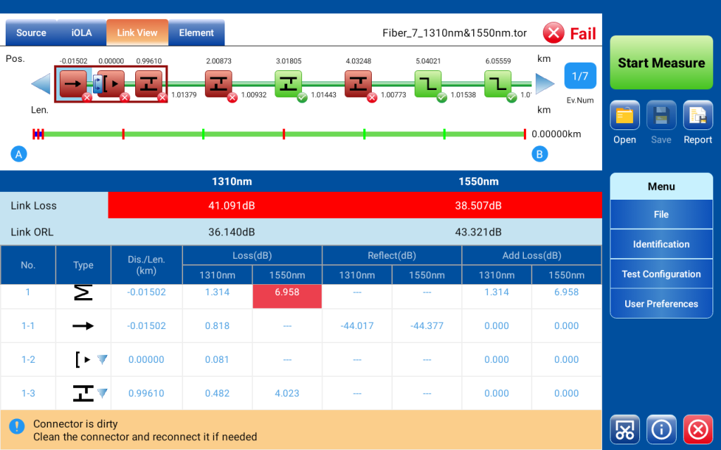
2.2 Innovative Application of Intelligent Optical Link Analysis (iOLA)
Traditional OTDR testing often requires technicians with extensive experience to accurately analyze complex links. The innovative Intelligent Optical Link Analysis (iOLA) feature of the RM7 Series fundamentally changes this. It can automatically identify various components like splitters, macrobends, and connectors, presenting test results in an intuitive link view.
For PON network testing involving splitters, the iOLA function can automatically set splitter ratios and loss thresholds, dramatically improving fiber optic testing efficiency. Even technicians without extensive experience can quickly pinpoint faults in complex networks using the RM7.
III. Test Parameter Settings and Optimization
3.1 The Relationship Between Pulse Width and Test Distance
In practical testing, the choice of pulse width directly affects the results. Wider pulses carry more energy, enabling testing over longer distances, but offer lower resolution. Narrower pulses provide high resolution but shorter test distances. The RM7 Series’ intelligent algorithms automatically optimize pulse width and test time based on the estimated link length, ensuring optimal trace quality for every test.
3.2 Precise Setting of Refractive Index and RBS Coefficient
Accurate refractive index (IOR) setting is paramount for measurement precision. The RM7 Series includes built-in default IOR values for different wavelengths (1310nm, 1550nm, 1625nm, etc.), and users can also customize these settings based on data from the fiber manufacturer. Equally important is setting the backscatter coefficient (RBS) , which directly impacts the calculation accuracy of reflectance and event loss.
IV. Practical Applications and Fault Diagnosis
4.1 Identifying and Locating Macrobend Events
Macrobends are common faults in fiber links. The RM7 Series accurately identifies macrobend events by comparing the loss values of different wavelengths (e.g., 1310nm and 1550nm) at the same location. When the loss for the longer wavelength is greater, and the difference exceeds a set threshold (default 0.5dB), the system automatically flags it as a macrobend event.
4.2 Pass/Fail Threshold Setting and Batch Testing
For scenarios requiring batch testing, the RM7 Series supports detailed Pass/Fail threshold settings, including splice loss, connector loss, reflectance, and fiber section attenuation. Upon test completion, the system automatically provides the pass/fail status for each event, significantly enhancing the readability and consistency of test reports.
Conclusion: Technological Innovation Driving Test Efficiency
As an R&D engineer at TFN, I understand that an excellent OTDR fiber tester needs to be not only accurate but also user-friendly. The RM7 Series is designed based on this philosophy, transforming complex OTDR principles into a convenient testing tool for engineers. Whether for long-haul backbone network testing or complex PON maintenance, the RM7 delivers reliable results with its high dynamic range, ultra-low dead zone, and Intelligent Optical Link Analysis capabilities.
TFN will continue to be deeply involved in the field of optical communication testing, driving continuous improvement in fiber optic testing efficiency through technological innovation. If you are interested in TFN RM7 Series OTDR, welcome to contact TFN Support Team:
Email: info@tfngj.com
WhatsApp: +86-18765219251
Or you can leave messages Here