


In the testing and maintenance of optical fiber networks, an OTDR (Optical Time Domain Reflectometer) is a core device for detecting optical fiber link loss and locating fault points. Event dead zone and attenuation dead zone are technical difficulties that must be overcome when using an OTDR, as they directly determine the accuracy of test data. As practitioners in optical fiber testing, mastering the definition, impact and avoidance methods of dead zones, combined with the hardware advantages of high-performance OTDR equipment, is the key to achieving accurate detection of optical fiber links. This article will analyze the two major dead zones of OTDR from a professional perspective, and explain how to avoid the impact of dead zones through equipment and operation optimization in combination with the technical parameters of the F7 series OTDR.
1. Event Dead Zone and Attenuation Dead Zone
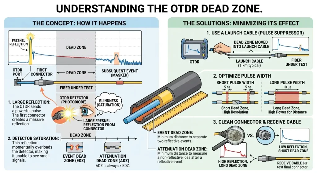
The essence of an OTDR dead zone is an area where the receiver is temporarily saturated due to the strong reflection of the test light by the optical fiber end face, making it impossible to identify subsequent optical fiber events or attenuation within a short distance. It is divided into two types: event dead zone and attenuation dead zone, which have completely different judgment criteria and physical meanings.
1.1 Event dead zone
It refers to the minimum distance from the reflection point at the optical fiber test end to the point where the OTDR can accurately identify the next reflection event, which corely reflects the OTDR’s ability to distinguish adjacent reflection events. Its calculation formula is: D_event = (c×τ)/2n, where c is the speed of light, τ is the receiver saturation recovery time, and n is the refractive index of the optical fiber ¹. This parameter determines whether the OTDR can detect short-distance reflection events such as connectors and fusion splices.
1.2 Attenuation dead zone
It refers to the minimum distance from the reflection point to the point where the OTDR can accurately measure the optical fiber attenuation coefficient, which corely reflects the OTDR’s loss detection capability for short-distance non-reflection events. The formula is: D_atten = (c×τ_atten)/2n, where τ_atten is the time for the receiver to recover from saturation to accurate loss detection. This parameter directly affects the loss measurement accuracy of short-distance optical fiber links.
2. The Actual Impact of OTDR Dead Zones on Optical Fiber Testing
In optical fiber engineering testing and daily maintenance, the existence of dead zones will directly lead to distortion of test data and even omission of key fault points, laying hidden dangers for the stability of optical fiber networks.
2.1 Impact of event dead zone
If there are multiple reflection events such as connectors and fusion splices at the near end of the optical fiber link, an excessively large event dead zone will cause the OTDR to be unable to distinguish adjacent events, resulting in “event overlap” and failure to accurately locate the fault point. This is particularly obvious in the testing of FTTH access optical fibers and computer room short jumpers.
2.2 Impact of attenuation dead zone
An excessively large attenuation dead zone will make the OTDR unable to accurately measure the attenuation coefficient of the near-end optical fiber, leading to deviations in the calculation of the total link loss. For short-distance and high-loss optical fiber segments (such as bent and extruded damaged segments), attenuation abnormalities may even be omitted, resulting in a decline in network transmission rate and signal packet loss.
In professional testing, errors caused by dead zones will directly affect the results of project acceptance, and also make later fault troubleshooting fall into a predicament of “inaccurate positioning and unclear loss”.
3. Practical Methods to Avoid the Two OTDR Dead Zones in Testing
Combined with industry practical experience and the operation logic of OTDR equipment, the core of avoiding event dead zone and attenuation dead zone is “equipment parameter optimization + standardized test operation”, and neither can be missing. The specific methods are as follows:
3.1 Select the narrow pulse width test mode
Pulse width is a core parameter affecting the dead zone. A narrow pulse width can shorten the receiver saturation time and reduce the dead zone range. For example, the TFN OTDR F7 series supports multi-gear pulse width adjustment from 5ns to 20000ns. Selecting narrow pulse widths such as 5ns and 10ns for near-end testing can effectively reduce the event dead zone and attenuation dead zone ².
3.2 Add test jump fibers (transmit fiber/receive fiber)
Connect a 1-2 km standard single-mode jump fiber between the OTDR test port and the tested optical fiber to move the near-end events of the tested optical fiber out of the OTDR dead zone range. The advanced settings support the custom of transmit fiber and receive fiber parameters, and the jump fiber length can be directly set on the device, allowing the test curve to automatically skip the dead zone segment.
3.3 Optimize the test parameter threshold
In the OTDR analysis settings, reasonably adjust the reflection threshold and non-reflection threshold to avoid the omission of weak reflection events at the near end due to excessively high threshold settings. The OTDR supports precise adjustment of the reflection threshold (0-40 dB) and non-reflection threshold (0-10 dB), which can adapt to the test requirements of different optical fiber links.
3.4 Adopt multi-wavelength comparative testing
Use 1310 nm and 1550 nm dual-wavelength or triple-wavelength testing. Different wavelengths have different dead zone characteristics, and the dead zone defects of a single wavelength can be compensated through curve comparison. The F7 series OTDR supports the basic dual wavelengths of 1310/1550 nm, and some models also support 1490/1625 nm to meet the comparative testing needs of multiple scenarios.
4. Dead Zone of the F7 OTDR: High-Precision Testing Achieved by Low Dead Zones
As a high-performance integrated OTDR, the TFN OTDR F7 series has achieved the ultimate optimization of dead zones in hardware design, and its official parameters and actual test performance are at the industry-leading level, reducing the impact of dead zones on testing from the hardware level:
4.1 Event dead zone as low as 0.8 m
Mainstream models of the TFN OTDR F7 such as S2/S3/S4/T1/T2 all have an event dead zone of 0.8m, and the M1/SM1 multimode/single-multimode integrated models have an event dead zone of 1m, which is far better than the conventional industry event dead zone of more than 1.5m ². It can accurately identify adjacent reflection events at the near end, perfectly adapting to the short-distance testing of computer room short jumpers and access optical fibers.
4.2 Attenuation dead zone stably at 6 m
The attenuation dead zone of the entire series is 6m ², which can quickly resume the accurate measurement of the near-end optical fiber attenuation. Even for short-distance optical fiber segments within 5m, the loss can be accurately calculated with the cooperation of jump fibers.
4.3 Supported by high resolution and precise ranging
The TFN OTDR F7 supports a high-resolution mode with a maximum sampling point of more than 256k, and the ranging accuracy is ±(0.75m + sampling interval + 0.005%×test distance) ². The combination of low dead zone and high resolution makes the position and loss of test data double precise, meeting the high-precision testing needs of communication operators, power and railway private networks and other fields.
In addition, the event map function of the TFN OTDR F7 can realize multi-pulse width testing and a visual event list, which can automatically mark all events outside the dead zone. Combined with the Pass/Fail threshold judgment, it allows testers to quickly distinguish qualified and unqualified links, further improving testing efficiency ².
5. Summary
The event dead zone and attenuation dead zone of OTDR are inevitable technical characteristics in optical fiber testing, but they are not insurmountable. As professional testers, we first need to understand the definition and impact of the two dead zones, and then avoid the dead zones through practical methods such as narrow pulse width selection, jump fiber addition and parameter optimization. At the same time, choosing a high-performance OTDR device with a low dead zone is the key.
The TFN OTDR F7 series, with a low event dead zone of 0.8m and an attenuation dead zone of 6m, combined with functions such as multi-pulse width adjustment, multi-wavelength testing and high-resolution sampling, solves the dead zone problem from both hardware and software levels and achieves high-precision testing of optical fiber links. In actual work, combining the advantages of equipment with standardized operations can make the test results of OTDR a reliable basis for the construction and maintenance of optical fiber networks.
If you are interested in TFN OTDR F7 Series, welcome to contact TFN Support Team:
Email: info@tfngj.com
WhatsApp: +86-18765219251
Or you can leave messages here