


Optical fiber loss mainly comes from three sources: transmission loss, additional loss and joint loss. In a full fiber loss test, the total loss of a link is calculated by summing the attenuation contributed by each component along the optical path. Accurate loss calculation is essential for evaluating the performance and reliability of any optical communication system.
As modern communication networks continue to evolve, optical fiber has become the backbone for long-distance, high-capacity data transmission. Thanks to its high bandwidth, low attenuation, and immunity to electromagnetic interference, optical fiber is the preferred medium for today’s high-speed networks. However, optical fiber is not completely lossless. Fiber loss remains one of the most important performance indicators, directly affecting signal quality and transmission distance.
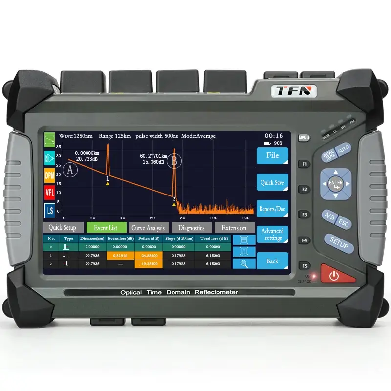
This article provides a clear and comprehensive overview of fiber loss standards and the calculation methods commonly used during a fiber loss test.
1. Standards for Optical Fiber Loss
It can generally be divided into three categories: transmission loss, additional loss, and joint (connector/splice) loss.
1.1 Transmission Loss
Transmission loss refers to the gradual weakening of optical power as light travels along the fiber. This attenuation is primarily caused by the fiber material’s intrinsic absorption, scattering, and especially Rayleigh scattering.
Typical benchmark values include:
- Standard single-mode fiber at 1550 nm: 0.2–0.3 dB/km
- Ultra-low-loss single-mode fiber (ULLF): as low as 0.15 dB/km or lower
These low-loss characteristics enable long-haul transmission with fewer amplifiers, making them ideal for metro and backbone networks.
1.2 Additional Loss
Additional losses arise from physical imperfections or environmental conditions affecting the fiber. These include:
- Bending loss: Occurs when a fiber is bent beyond its minimum bending radius, causing leakage into the cladding.
- Inhomogeneity loss: Caused by variations in core or cladding refractive index.
- Material scattering loss: Typically the result of impurities, micro-defects, or air bubbles in the glass.
While usually small, these losses can become significant in long-distance or high-precision applications.
1.3 Joint Loss (Connector and Splice Loss)
Joint loss occurs during fiber connection and is influenced by factors such as contamination, misalignment, polishing quality, and connector type.
Common connector standards include FC, SC, LC, ST, each offering different performance characteristics.
- Well-polished connectors often show losses of 0.2–0.75 dB per connector.
- Poor-quality or dirty connectors can introduce far higher insertion loss.
Since each connector contributes to total link loss, proper connector selection and maintenance are critical during a fiber loss test.
2. Calculation Methods for Optical Fiber Loss
Fiber link loss is calculated by adding the attenuation from cables, connectors, and splices. These values help determine whether a link meets design requirements and whether additional power margin is required.
2.1 Cable Attenuation
Cable attenuation (fiber attenuation per unit length) is typically expressed in dB/km.
Formula:
Cable Attenuation (dB) = Fiber Attenuation Coefficient (dB/km) × Fiber Length (km)
Example:
A 1310 nm single-mode fiber with an attenuation coefficient of 0.5 dB/km over 10 km:
→ 0.5 × 10 = 5 dB
2.2 Connector Attenuation
Connector attenuation refers to the insertion loss introduced by fiber connectors.
Formula:
Connector Attenuation (dB) = Number of Connector Pairs × Insertion Loss (dB)
Example:
Two ST connectors, each with max loss of 0.75 dB:
→ 0.75 × 2 = 1.5 dB
2.3 Splicing Attenuation
Splicing loss occurs when two fibers are fusion-spliced.
Formula:
Splicing Attenuation (dB) = Number of Splices × Splice Loss (dB)
According to the TIA/EIA standard, the typical maximum splice loss is 0.3 dB.
3. Total Fiber Link Loss Calculation
The total optical link loss is the sum of all individual losses measured during a fiber loss test.
Total Link Loss (LL) = Cable Attenuation + Connector Attenuation + Splicing Attenuation
Example Scenario
- Fiber distance: 10 km, 1310 nm
- Cable attenuation: 5 dB
- Two ST connectors: 1.5 dB
- One splice: 0.3 dB
Total Loss:
5 dB + 1.5 dB + 0.3 dB = 6.8 dB
This value is then compared against system power budgets to confirm whether the link meets design requirements.
In practical deployments, engineers also include a power margin (3–6 dB) to account for future degradation, connector contamination, or maintenance operations.
Conclusion
As a key performance metric, optical fiber loss directly affects transmission capacity, signal quality, and network reliability. Understanding the standards and mastering the calculation process allows engineers to design and maintain stable, high-performance optical networks.
With continuous advancements in fiber manufacturing and installation technology, fiber attenuation is expected to decrease further, enabling even higher-capacity and longer-distance optical communication systems.
Whether during installation, troubleshooting, or routine maintenance, performing an accurate fiber loss test remains essential for ensuring optimal network performance.