


After years in this line of work, you come to understand one fundamental truth: In cable installation and maintenance, the dynamic range of the OTDR in your hand directly determines how far and how clearly you can “see.” On site, colleagues often ask me, “Why can’t my OTDR test a long distance? Or why is the tail end of the trace all noise, making it unusable?”
In reality, the most critical parameter behind this issue is the OTDR’s Dynamic Range. Today, let’s discuss how this parameter actually affects our testing from the perspective of a frontline cable installer, and using the TFN equipment we commonly use, explain how to choose the right model for long-distance fiber testing.
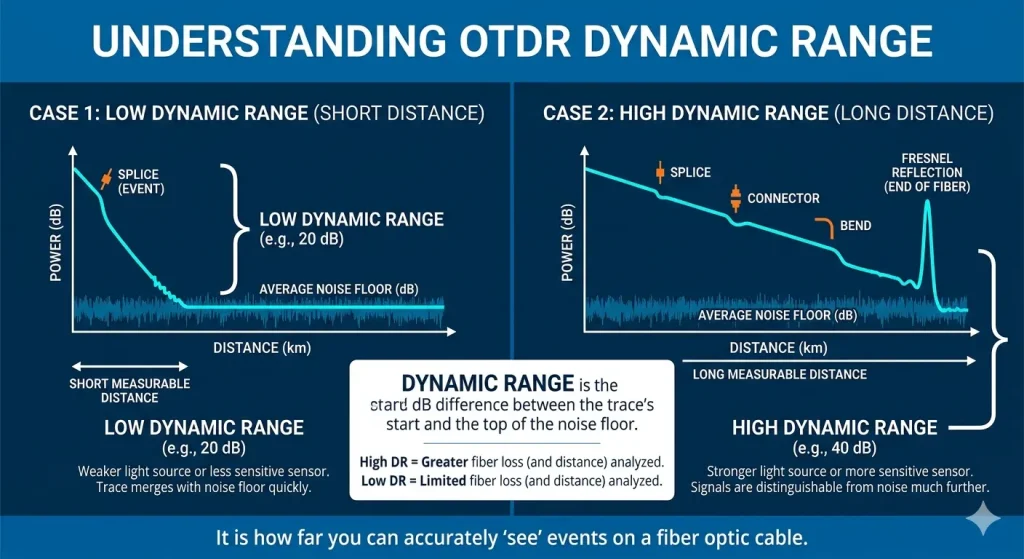
What is OTDR Dynamic Range?
Simply put, dynamic range is the difference, measured in dB, between the backscattered light signal detected by the OTDR at the starting point and the noise floor. Think of it like a flashlight beam – the stronger the beam (the larger the dynamic range), the farther it can illuminate.
For engineers, a larger dynamic range means two good things:
1. Testing Further: It enables testing of ultra-long distance backbone cables.
2. Seeing More Clearly: At the same distance, the signal-to-noise ratio of the trace is higher, making it easier to identify subtle bends or splice points with higher loss.
According to IEC standards, dynamic range is typically measured using the “three-point” or “five-point” method to eliminate the effects of dead zones. But in our emergency repair work, we care more about whether the “typical dynamic range” specified on the device can handle the complex total loss of the live link.
How Does Dynamic Range Limit Your Test Distance?
Many people mistakenly believe that if an OTDR claims to test 100km, it can actually test 100km. This is a misconception. Test Distance = (Dynamic Range — Total Link Loss — Safety Margin) / Fiber Attenuation Coefficient.
For example, you’re laying standard G.652.D single-mode fiber with a typical attenuation coefficient of 0.2 dB/km at the 1550nm window. If you use an OTDR with a 32dB dynamic range (like the TFN F1 model) to test a link containing 3 splice points (assuming total loss 0.5dB) and 2 connectors (assuming total loss 1dB), the maximum test distance would be approximately: (32dB – 1.5dB – 3dB safety margin) / 0.2 ≈ 137 km.
But if the link includes splitters (like a 1:32 splitter in a PON network, with a loss of over 16dB), then a 32dB dynamic range might not even penetrate 10km effectively. This is precisely why we must consider dynamic range redundancy in complex FTTH or long-haul backbone projects.
Citations:
- Source: National Institute of Standards and Technology (NIST) – Technical Note “Fiber Optic Test and Measurement” – 2020
- Source: IEEE Photonics Society – “Impact of Dynamic Range on Optical Time-Domain Reflectometer Performance in Long-Haul Networks” – 2021
Pulse Width and Dynamic Range: An Unavoidable Double-Edged Sword
When adjusting OTDR parameters on site, many beginners overlook the importance of Pulse Width settings. A wider pulse width means more powerful light is launched, naturally resulting in a larger dynamic range. But the trade-off is a larger Dead Zone.
This means if you want to see far (large dynamic range), you have to accept that near-end events (like the first connector) might not be accurately measured. If you want clear near-end details (small pulse width, small dead zone), you might not be able to reach far distances.
Modern equipment, like the TFN F7 series we frequently use, features optimized optical design. It provides a high dynamic range of up to 45dB while maintaining an event dead zone as low as 0.8m. This capability to handle both troubleshooting patch cords near the equipment (requiring small dead zone) and locating backbone breaks (requiring high dynamic range) genuinely saves us time on site.
TFN OTDR Series: Professional Choices for Different Distances
TFN OTDR testers strike a good balance between cost-effectiveness and professional capability. To help you understand the relationship between dynamic range and distance, there’s a table based on our actual project experience:
| TFN Model | Faixa dinâmica (dB) | Max Test Distance (km) | Applicable Scenarios | Core Advantages |
| MN3 | 28/26 | 100 | FTTH access networks, building cabling, patch cord testing | Extremely portable, touchscreen interface, ideal for quick fault location in the last mile. |
| F1 | 32/30 | 120 | Metro networks, campus networks, short to medium distance lines | Handheld design, multi-function integration (OPM/VFL), excellent cost-performance. |
| F7 | Max 45/43 | > 180 | Long-haul backbones, core networks, ultra-long distance lines | High dynamic range + low dead zone, supports live PON testing, suitable for carrier-grade trunk maintenance. |
| RM7 | Max 50/48 | > 240 | Ultra-long spans (e.g., short-distance submarine cables, desert/mountain lines), complex link analysis | Modular platform, top-tier dynamic range, features intelligent link analysis (iOLA) and professional report generation. |
Practical Advice for Long-Distance Testing
1. Build in Margin: When selecting equipment, don’t choose based purely on theoretical values. For an 80km line, 30dB might seem barely sufficient on paper. However, considering factors like fiber aging, higher-than-expected splice loss, and bending, I strongly recommend choosing equipment with a dynamic range above 40dB, like the TFN F7. The extra 10dB translates directly into hours saved on-site troubleshooting.
2. Pay Attention to Signal-to-Noise Ratio: The last few dB of the dynamic range are often accompanied by noise. If the device’s signal-to-noise ratio processing isn’t good, the far-end trace will jitter like an ECG. High-quality devices, such as the TFN RM7, not only have a large dynamic range but also use high-resolution sampling (e.g., 256k sample points) and advanced digital signal processing algorithms to ensure far-end events remain clearly discernible.
3. Special Considerations for PON Testing: With the widespread adoption of FTTH, the extensive use of splitters dramatically increases link loss. Standard OTDRs might mistakenly identify a splitter as a break. TFN’s F7 and RM7 series feature dedicated PON testing modes (using 1625/1650nm test wavelengths and filters) that can penetrate splitters and directly test the fiber quality at the end-user’s premises. This is particularly useful during optical network upgrade project acceptance.
Conclusão
For those of us who work with fiber optic cables daily, the OTDR is our “eye.” The size of its dynamic range determines how far this eye can see and how clearly it can see through noise.
Choosing the right OTDR isn’t just about looking at the numbers on a spec sheet; it’s about ensuring it can perform reliably in the specific link scenarios you’re responsible for. Whether it’s the flexible and portable TFN MN3 or the high-performance TFN RM7, understanding the relationship between dynamic range and test distance allows you to select the right tool for the job every time, helping you succeed in the field.
- Source: Optical Society of America (OSA) – “Journal of Lightwave Technology: Advances in OTDR Dead Zone and Dynamic Range Optimization” – 2022
TFN offers OTDRs suitable for various scenarios. If you are interested in TFN optical time domain reflectometers, Entre em contato com a equipe de suporte da TFN:
E-mail: info@tfngj.com
WhatsApp: +86-18765219251
Ou você pode leave messages here
Perguntas frequentes
OTDR dynamic range refers to the difference (in dB) between the backscattered signal at the start of the fiber and the noise floor. A higher dynamic range allows technicians to test longer distances and obtain clearer traces, making it easier to detect splice loss, bends, and faults in fiber optic links.
The higher the dynamic range, the farther an OTDR can effectively test. In practical terms, test distance depends on dynamic range minus total link loss and safety margin, divided by the fiber attenuation coefficient. Insufficient dynamic range results in noisy traces and limits usable measurement distance.
Noise at the end of an OTDR trace usually occurs when the signal approaches the device’s noise floor. This happens when the dynamic range is too low for the tested link, or when total link loss (connectors, splices, splitters) is too high.
For long-distance fiber links (e.g., 80–150 km), it is recommended to use an OTDR with at least 40 dB dynamic range. This ensures sufficient margin for unexpected losses, fiber aging, and environmental factors, improving testing reliability.
Optical splitters significantly increase link loss. For example, a 1:32 splitter can introduce over 16 dB loss, drastically reducing test distance. In such cases, high dynamic range OTDRs and dedicated PON testing modes are required to accurately measure the link.