


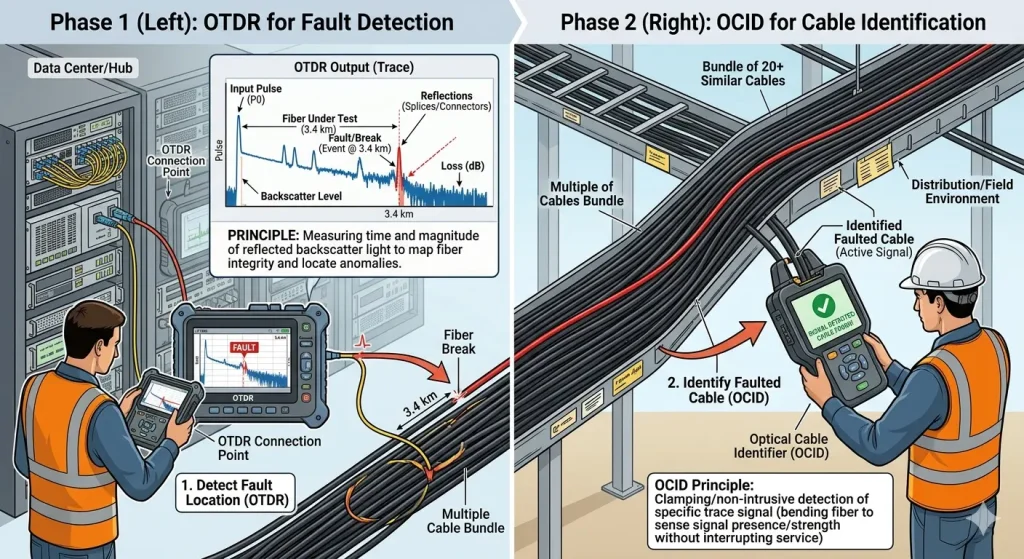
In the field of optical cable maintenance and emergency repair, engineers often face two core challenges: accurately identifying the target cable among numerous others, and quickly locating fault points within the fiber link. In the past, these tasks required carrying two separate devices—an optical cable identifier and an OTDR—which not only increased equipment costs but also reduced on-site operational flexibility and efficiency. The GP200 ocid tester, which integrates an optical cable identifier and OTDR into a single handheld device, offers communication engineers a comprehensive field testing solution.
The Core Function of Optical Cable Identifiers
An optical cable identifier, as the name suggests, is designed to accurately identify target cables without causing any damage. The GP200 series operates based on the elasto-optic effect and the principle of optical interference. When laser light travels through an optical fiber, any external tapping or vibration on the cable alters the interference pattern of the light waves within the fiber. The device detects these changes in light intensity and converts them into visual signals and audio feedback.
In practice, the field engineer simply taps the suspected cable lightly, while the operator at the near end observes the vibration amplitude changes on the GP200’s screen, displayed in either electrocardiogram or bar graph mode, and simultaneously hears the corresponding tapping sound through headphones. This dual feedback mechanism significantly improves identification accuracy, completely replacing traditional destructive methods such as cutting, bending, or freezing. Notably, the device supports single-fiber testing without requiring a loopback at the far end, enabling reliable target cable identification even when the fiber termination is an APC connector or when the fiber is broken.
The OTDR Function: Precise Fiber Fault Location
The OTDR (Optical Time Domain Reflectometer) module integrated into the GP200 series utilizes the principles of Rayleigh scattering and Fresnel reflection to accurately measure fiber length, transmission attenuation, splice loss, and fault locations. After completing cable identification, engineers can immediately switch to OTDR mode without changing equipment, allowing them to perform link quality analysis on the identified cable.
In terms of parameter settings, the GP200 offers a variety of adjustable parameters, including laser wavelength (1310 nm/1550 nm), distance range (auto to 180 km), and pulse width (5 ns to 20.48μs). For routine maintenance scenarios, it is recommended to begin with the auto distance range and auto pulse width for a quick test, allowing the system to automatically select the optimal settings based on the actual fiber length. When analyzing specific event points, manual mode can be used in conjunction with the A/B cursor function to zoom in horizontally and vertically on the trace, accurately calculating loss and attenuation coefficients between two points.
On-Site Application Advantages of the Integrated Design
Integrating the optical cable identifier with OTDR functionality into a single device provides significant efficiency gains for field engineers. In scenarios such as fiber cutovers or emergency repairs, the traditional process typically involves first identifying the target cable using an optical cable identifier, then switching equipment or waiting for a colleague to bring an OTDR for fault location. With the GP200 series, after completing cable identification, the engineer can immediately switch to OTDR testing, eliminating the time wasted on equipment changes and repeated connections.
Furthermore, the GP200 achieves software-level functional synergy. After completing the line end setting in OCID mode, the system automatically records the link length information. When switching to OTDR testing, this information can serve as a reference, helping engineers quickly set appropriate test distance ranges. The device also supports multi-trace analysis, allowing up to four test traces from different times or wavelengths to be compared in a single window, facilitating analysis of fiber link changes over time.
Key Points and Precautions for Field Operations
When using the GP200 for cable identification, several key points require attention. First, the OCID optical interface uses an FC/APC connector. Before testing, all optical interfaces and patch cord end faces must be cleaned thoroughly. Use a cleaning swab moistened with anhydrous alcohol and wipe in a clockwise direction to ensure no residue remains. Second, when tapping cables on site, separate the target cable from others by at least one meter. Use a metal tool to tap at a steady rhythm of once per second to avoid vibration crosstalk caused by tightly bundled cables.
For OTDR testing, it is recommended to keep the “in-fiber light alarm” function enabled in the parameter settings to prevent the test pulse from interfering with communication signals. If test results show excessive noise, increase the measurement duration or adjust the pulse width. If event points are not fully detected, reduce the pulse width range and increase the test time.
Conclusão
The GP200 series, which integrates an optical cable identifier and OTDR, combines the core functions of a fiber optic cable identifier tool with those of an optical time domain reflectometer into a single, efficient, and portable field testing solution. This device not only meets the need for rapid target cable identification during cable tracing but also handles precise fault location in fiber links. It operates reliably in various environments, including ducts, manholes, tunnels, and aerial installations. For telecommunications carriers, engineering maintenance teams, and network construction departments, this integrated testing tool effectively reduces equipment investment, shortens fault handling times, and improves overall operational efficiency.
Se você estiver interessado em GP200 optical cable identifier, Entre em contato com a equipe de suporte da TFN:
E-mail: info@tfngj.com
WhatsApp: +86-18765219251
Ou você pode leave messages here
Perguntas frequentes
The most effective way to identify a target cable non-destructively is by using an identificador de cabo óptico that utilizes the elasto-optic effect. By lightly tapping the suspected cable, the device (like the GP200) detects minute changes in light interference patterns caused by the vibration. It then converts these changes into visual and audio signals, allowing engineers to confirm the correct cable without interrupting service or causing physical damage.
Integrating OTDR and OCID into a single handheld unit significantly improves field operational efficiency. Instead of carrying two separate devices, engineers can identify a cable and immediately switch to OTDR mode to analyze link quality or locate faults. This eliminates the need for repeated fiber connections, reduces equipment costs, and speeds up emergency repair times in complex environments like manholes or aerial installations.
Yes. Modern identification tools like the GP200 series support single-fiber testing that does not require a loopback at the far end. This makes it possible to accurately identify target cables even when the fiber termination uses an APC connector or if there is a complete break in the link, providing high reliability during emergency cutovers.
For standard maintenance, it is best to start with Auto Mode, where the device automatically selects the optimal distance range and pulse width based on the fiber length. For more detailed analysis of specific events (like splice loss or bends), switch to Manual Mode. Using the A/B cursor function allows you to zoom in on the trace to precisely calculate attenuation coefficients and loss between two specific points.
To ensure an accurate reading, separate the target cable from the surrounding bundle by at least one meter whenever possible. When tapping, use a steady rhythm of approximately one tap per second. Additionally, ensure all optical interfaces are cleaned with anhydrous alcohol and a lint-free swab before connection to prevent signal noise and protect the FC/APC interface.