OTDR Usage Guide: How to Accurately Select the Test Range of an Optical Time Domain Reflectometer?
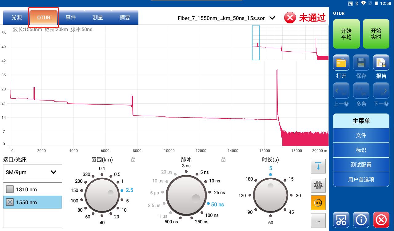
In fiber optic network maintenance and acceptance, the Optical Time Domain Reflectometer (OTDR) is a core tool for diagnosing link quality. The choice of test range directly impacts measurement accuracy and efficiency: too low a range can miss far-end events, while too high a range reduces resolution and signal-to-noise ratio. This article uses the TFN RM7 series OTDR as an example to analyze range selection strategies for three typical scenarios.
1. Short-distance Precision Testing (<5km)
Applicable Scenarios
High-precision testing of equipment room patch cords, vertical cabling in buildings, and other applications requires locating meter-level events (such as connector degradation and microbend loss).
RM7 Operation Guidelines
1.1. Range Setting: Select a range ≥ actual distance × 1.5 (e.g., select a 5km range for a 3km link).
1.2. Pulse Width: Enable narrow pulses between 10ns and 30ns (RM7 supports a minimum of 10ns).
1.3. Wavelength Selection: For short distances, 1310nm is preferred (strong Rayleigh scattering, resulting in clearer event details).
Note: When the range is too large, narrow pulse signals are attenuated more severely, potentially causing far-end noise to overwhelm valid signals.
2. Medium- and Long-Distance Full-Link Analysis (5km-100km)
Applicable Scenarios
Metropolitan access networks and campus backbone fiber acceptance require a balance between event resolution and dynamic range.
RM7 Smart Solution
2.1. AutoRange: The device automatically adjusts to the optimal range.
2.2. Pulse Width Step Adjustment:
Use 100ns pulses for the first 10km to accurately locate events.
Switch to 300ns pulses beyond 10km to enhance signal-to-noise ratio.
2.3. Multi-Wavelength Collaboration:
Detect near-end events at 1310nm.
Analyze far-end attenuation at 1550nm/1625nm.

3. Ultra-Long-Haul and High-Loss Links (>100km)
Applicable Scenarios
In high-loss environments such as trans-sea optical cables and primary trunk lines, the core requirement is to push the limits of dynamic range.
RM7 Key Technologies
1. Range Redundancy: Actual distance × 2 (e.g., a 150km link uses a 300km range).
2. Large Pulse Width: 1μs-10μs pulses (RM7 supports up to 20μs).
3. Low-Loss Wavelength: 1625nm window preferred (lowest fiber attenuation coefficient).
4. Intelligent Noise Reduction: Extends test time to 180s+, improving curve smoothness.
Golden Rules for Range Selection
Based on TFN RM7 test data:
Link Length |
Recommended Range |
Pulse Width |
Test Time |
<2km |
5km |
10-30ns |
15s |
2-50km |
Distance X 1.8 times |
100-500ns |
30-60s |
>50km |
Distance X 2 times |
1μs-10μs |
90-180s |
Key Tips: The RM7's multi-wavelength parallel testing function simultaneously acquires data at 1310/1550/1625nm, generating a full-band analysis report in a single measurement, significantly improving long-distance testing efficiency.
Avoid Three Major Operational Mistakes
1. Equating range to actual distance → Far-end events may be truncated
2. Using a single pulse width throughout → Near-end oversaturation and high far-end noise
3. Ignoring fiber type → Multimode fiber requires 850nm+ small pulses (the RM7 automatically identifies fiber type).
By precisely matching range, pulse, and wavelength, the TFN RM7 series OTDR can maintain event location accuracy within ±0.5m, significantly improving fiber diagnostic efficiency. Remember: greater range isn't always better; more "intelligent matching" is always better.
