


La fusionadora de fibra es un dispositivo fundamental en la ingeniería de comunicaciones ópticas, y su rendimiento repercute directamente en la calidad y la eficacia del empalme de fibras. Este artículo ofrece un desglose en profundidad de la construcción de la empalmadora por fusión de fibra desde la perspectiva de un ingeniero de investigación y desarrollo. Detalla la función de cada componente externo e interno y su influencia en los parámetros clave de rendimiento de la máquina, ofreciendo a los lectores una comprensión exhaustiva de los principios de funcionamiento y la lógica de diseño de este instrumento de precisión.
Visión general y principio básico de funcionamiento de la fusionadora de fibra óptica
Una empalmadora por fusión de fibra es un dispositivo que utiliza un arco eléctrico de alta tensión para fundir y fusionar las caras extremas de dos fibras ópticas. Esto crea una conexión permanente, de bajas pérdidas y alta resistencia, logrando un acoplamiento preciso de los modos de fibra para garantizar una transmisión eficaz de la señal óptica. En los sistemas de comunicación óptica, el rendimiento de la empalmadora afecta directamente a la pérdida de enlace, la fiabilidad y la estabilidad a largo plazo.
Análisis de la estructura externa: Función e impacto en el rendimiento
1. Carcasa y estructura de protección
La carcasa proporciona soporte mecánico y ofrece protección contra el polvo, los golpes y la disipación del calor. Una carcasa de alta calidad protege eficazmente los componentes internos de precisión, mejorando la durabilidad del dispositivo en entornos de ingeniería de campo.
2. Cubierta antiviento y ranura en V
La cubierta antiviento aísla el flujo de aire exterior para garantizar la estabilidad del arco. La ranura en V asegura y guía la posición de la fibra. Su precisión de mecanizado afecta directamente a la precisión de alineación de la fibra, por lo que es un factor crítico que influye en la pérdida de empalme.
3. Electrodos y portaelectrodos
Los electrodos generan el arco de alta tensión. Su material y vida útil están relacionados con la estabilidad de la descarga. El diseño del portaelectrodos influye en la concentración del arco y la distribución de la energía, afectando así a la resistencia y consistencia del empalme.
4. Horno de termorretracción y bandeja de enfriamiento
El horno de calentamiento se utiliza para la protección de manguitos termorretráctiles, garantizando una protección fiable del punto de empalme. La bandeja de enfriamiento controla la velocidad de enfriamiento para evitar la pérdida de microflexión causada por el estrés térmico.
5. Rendimiento de la batería y resistencia
La capacidad de la batería y los circuitos de gestión de energía determinan la capacidad operativa de la empalmadora en entornos sin fuentes de alimentación externas, lo que repercute directamente en el tiempo de funcionamiento continuo y la eficacia en las obras.
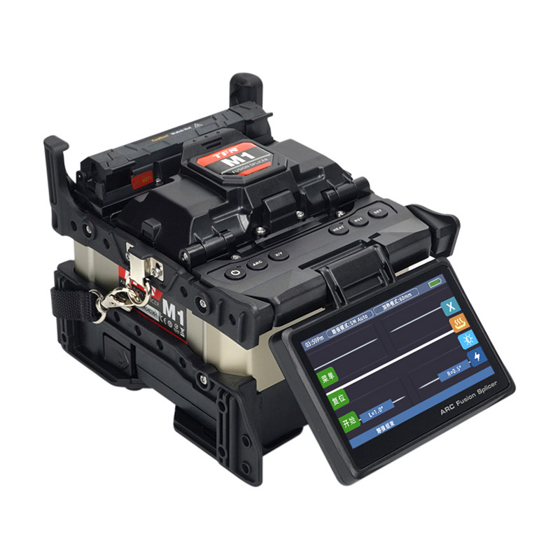
6. Pantalla e interfaz de funcionamiento
El diseño de funcionamiento dual, que combina una pantalla táctil de alta definición y botones físicos, equilibra la practicidad y la adaptabilidad operativa, lo que influye en la eficacia del dispositivo en diferentes escenarios de ingeniería y hábitos de usuario.
Análisis de la estructura interna: Sistemas centrales y motores de rendimiento
1. Placa de circuito principal y sistema de control
La placa de circuito principal integra la unidad central de procesamiento (CPU), la gestión de la alimentación y los módulos de accionamiento del motor, y actúa como “cerebro” de la empalmadora por fusión. Su optimización de algoritmos y su capacidad de control en tiempo real determinan directamente la precisión de la alineación, el control del arco y la velocidad de empalme.
2. Sistema motor y mecanismo de alineación del núcleo
El número y el tipo de motores (motores de avance, motores de alineación, motores de enfoque) influyen directamente en el método de alineación y en la precisión. Por ejemplo:
Sistemas de cuatro motores lograr la alineación del revestimiento, adecuado para proyectos generales de corta distancia.
Sistemas de seis motores soportan la alineación del núcleo, ideal para proyectos de líneas troncales de larga distancia y alta precisión.
3. Sistema óptico de imágenes
Incluye el objetivo, el sensor CMOS y los circuitos de procesamiento de imágenes. Captura imágenes en tiempo real de los extremos de las fibras y evalúa de forma inteligente el ángulo de corte y la calidad de los extremos. La claridad de la imagen y la velocidad de procesamiento son factores clave que afectan a la tasa de éxito del empalme y a la estabilidad de las pérdidas.
4. Paquete de alta tensión y sistema de generación de arco
El paquete de alta tensión suministra alta tensión estable a los electrodos. Su estabilidad de salida y velocidad de respuesta afectan directamente a la consistencia de la energía del arco, lo que determina la resistencia mecánica y el rendimiento óptico del punto de empalme.
5. Sistema de sensores
Los sensores de temperatura, humedad y presión supervisan los parámetros ambientales en tiempo real y envían los datos al sistema de control para ajustar dinámicamente los parámetros de descarga. Esto garantiza una calidad de empalme estable en altitudes y condiciones climáticas variables.
Sinergia de los componentes y correlación con los parámetros de rendimiento
- Pérdida de empalme: Afectada conjuntamente por la precisión de la ranura en V, el sistema de alineación del motor, la claridad de la imagen y la estabilidad del arco.
- Eficacia de empalme: Estrechamente relacionada con la velocidad de respuesta del motor, los algoritmos de procesamiento del sistema y los procedimientos operativos optimizados.
- Adaptabilidad medioambiental: Se consigue gracias al sistema de sensores, el diseño a prueba de viento y la gestión de la energía, lo que garantiza un funcionamiento fiable en entornos complejos.
- Vida útil: Determinada por el material del electrodo, la durabilidad de la estructura mecánica, la protección del circuito y el diseño de la disipación del calor.
Conclusión: Selección de una empalmadora basada en la estructura para su proyecto
Comprender la estructura interna y externa de una empalmadora por fusión de fibra ayuda a los ingenieros a seleccionar la configuración de dispositivo adecuada en función de los tipos de proyecto específicos (por ejemplo, FTTH, redes metropolitanas, líneas troncales de largo recorrido). Por ejemplo, los proyectos de corta distancia pueden utilizar un sistema de cuatro motores, mientras que los proyectos de larga distancia y alta precisión deben emplear un modelo de alineación de núcleo de seis motores. Además, la limpieza periódica, el mantenimiento, la sustitución de electrodos y la calibración del sistema son prácticas esenciales para mantener el funcionamiento de alto rendimiento del equipo a largo plazo. Si desea más información sobre la tecnología y las aplicaciones de las fusionadoras de fibra óptica, póngase en contacto con nosotros. póngase en contacto con el equipo técnico y de asistencia de TFN.
Palabras clave para este artículo: Empalmadora por fusión de fibra, Estructura de la empalmadora por fusión de fibra, Cómo funcionan las empalmadoras por fusión de fibra, Parámetros de rendimiento de la empalmadora por fusión de fibra, Sistemas de motor de la empalmadora por fusión, Tecnología de alineación de fibra, Control de pérdidas por empalme, Guía de mantenimiento de la empalmadora por fusión de fibra, Equipos de empalme de fibra de alta precisión, Elección de herramientas de ingeniería de fibra óptica.