


As a communications engineer who spends countless days in the field holding a spectrum analyzer, my feelings towards the word “antenna” are quite complex. It serves as our tactile sensor to perceive the wireless world, yet it is often the most troublesome variable in interference hunting. The correct choice of antenna directly determines whether you work efficiently or waste valuable energy. This article systematically reviews antenna classification from an engineering application perspective and, using the TFN RMT series RF spectrum analyzers and the TM9265 directional antenna set in practical scenarios, discusses the fundamental differences between omnidirectional and directional antennas in spectrum testing.
I. Basic Logic of Antenna Classification
Based on radiation characteristics, antennas are primarily divided into two categories: omnidirectional antennas and directional antennas. Omnidirectional antennas radiate uniformly 360° in the horizontal plane, suitable for signal surveys and field strength coverage measurements; directional antennas focus energy in a specific direction, offering higher gain and front-to-back ratio, making them ideal for interference source localization and base station signal analysis [1].
Antennas can be further categorized by frequency band into very low frequency (VLF) antennas, high frequency (HF) antennas, ultra-high frequency (UHF) antennas, and microwave antennas. This article focuses on the 30MHz–8GHz band commonly used in handheld spectrum analyzers, as well as the 6GHz–26.5GHz microwave band.
II. Omnidirectional Antennas: The “Standard” for Spectrum Analysis
In routine spectrum monitoring, the omnidirectional antenna is our first choice. Taking the TFN RMT series handheld spectrum analyzer as an example, the standard omnidirectional antenna typically covers from 9kHz to 6.3GHz or higher frequencies. It is primarily used for fundamental functions like spectrum scanning, field strength measurement, and occupied bandwidth analysis.
The advantage of an omnidirectional antenna lies in its “no-blind-spot” characteristic. When entering an unfamiliar environment, we first need to use an omnidirectional antenna for a quick sweep across the entire frequency band to understand the background noise and signal distribution. In this scenario, we don’t need to know where the signal comes from, only “what” is present.
Key Parameters: Omnidirectional antennas typically have low gain, generally between 0dBi and 3dBi, with a Voltage Standing Wave Ratio (VSWR) of less than 2.0 to ensure broadband matching characteristics.
III. Directional Antennas: The “Sniper Rifle” for Interference Hunting
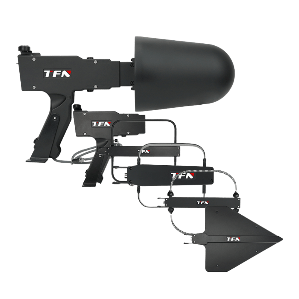
When we need to ask the further question, “where does the signal come from?”, the directional antenna takes center stage. The TFN TM9265 handheld direction-finding antenna set covers 9kHz to 26.5GHz and includes several directional antennas like the F200, F250, F580, FG626, along with the W3 amplifier handle. It is an essential tool for interference localization and base station analysis.
3.1 Application of Directional Antennas in Interference Signal Localization
In interference hunting, we often employ the “approximation method”: holding the directional antenna, gradually rotating to find the direction of the maximum signal level, and finally pinpointing the interference source location. The TM9265 series utilizes a large tone-to-noise ratio amplitude comparison direction-finding system. Coupled with an electronic compass, it provides real-time direction of arrival information, significantly improving hunting efficiency.
Taking the F580 (500MHz~8GHz) as an example, its typical gain can reach 6dBi, with a front-to-back ratio greater than 10dB. This effectively suppresses interfering signals arriving from the rear, ensuring accurate direction judgment [2].
3.2 Application of Directional Antennas in Base Station Analysis
During 5G NR base station testing, the TFN RMT series, combined with a directional antenna, enables specific cell beam ID locking, PCI tracking, and measurements of indicators like SS-RSRP. Since 5G utilizes Massive MIMO beamforming technology, signals exhibit strong directivity. Using an omnidirectional antenna makes it difficult to accurately capture the signal characteristics of the target cell; relying on a directional antenna for “point-to-point” measurement is essential.
For example, in FDD-LTE testing, a directional antenna helps distinguish between main lobe and side lobe signals, avoiding distortion of demodulation metrics caused by multipath interference. The RMT series supports a real-time analysis bandwidth of up to 100MHz. Combined with a directional antenna, it can perform uplink and downlink separation interference hunting tests for TDD systems.
IV. Microwave Antennas: The “Special Forces” for High-Frequency Testing
As the frequency enters the range above 6GHz, particularly the microwave band (6GHz~26.5GHz), antenna design faces greater challenges. The FG626 horn antenna in the TM9265 set covers 6GHz~26.5GHz, boasting a high gain of 12dBi~20dBi. It is suitable for satellite communications, microwave link testing, and 5G millimeter-wave interference analysis.
Microwave antennas typically possess stronger directivity and higher gain, but this also means a narrower beamwidth, demanding extremely high alignment accuracy. In practical drive testing, we often use tripods and fine-tune with the help of electronic compasses.
V. Theoretical Support and Academic Basis
The relationship between an antenna’s directivity (D) and gain (G) can be expressed as:
G = η* D
donde η is the antenna efficiency, and D is the directivity [3]. Directional antennas increase received signal strength in a specific direction by increasing D, thereby concentrating energy.
In interference localization, the Front-to-Back Ratio (FBR) is a key indicator of directional performance, defined as:
FBR = 10 * log10 * ( Pfront / Pback )
donde Pfront is the power in the main lobe direction, and Pback is the power in the back lobe direction [4]. The TM9265 series achieves an FBR greater than 10dB, ensuring localization accuracy.
VI. Summary and Selection Recommendations
Omnidirectional Antennas: Suitable for spectrum surveys, field strength coverage, and routine monitoring. Representative scenario: Initial scanning with the TFN RMT handheld spectrum analyzer.
Directional Antennas: Suitable for interference source localization, base station analysis, and signal tracking. Representative scenario: The TM9265 used with the RMT for 5G NR beam analysis.
Microwave Antennas: Suitable for specialized high-frequency testing, such as satellite communications and millimeter-wave interference hunting.
If you want to know more about the difference of antennas and TFN TM9265 directional antenna, Póngase en contacto con el equipo de asistencia de TFN:
Correo electrónico: info@tfngj.com
WhatsApp: +86-18765219251
O puedes leave messages here
Referencias:
[1] Balanis, C. A. Antenna Theory: Analysis and Design. 4th ed., Wiley, 2016.
[2] Kraus, J. D., & Marhefka, R. J. Antennas for All Applications. 3rd ed., McGraw-Hill, 2002.
[3] IEEE Standard Definitions of Terms for Antennas. IEEE Std 145-2013, 2013.
[4] Stutzman, W. L., & Thiele, G. A. Antenna Theory and Design. 3rd ed., Wiley, 2012.