


Understanding the different event types in an OTDR helps users more accurately locate and resolve issues within optical fiber links.
An OTDR (Optical Time Domain Reflectometer) is a commonly used testing instrument in the field of fiber-optic communications. It identifies and analyzes various problems in optical fiber cables by measuring reflected and backscattered light signals. In OTDR test results, different event types are displayed on the trace with specific symbols and parameters, providing important reference information for fiber maintenance and optimization.
Below is a clear explanation of the common OTDR event types.
1. Span Start and Span End
The span start and span end indicate the beginning and end of a fiber span. By default, the span start is the first event on the fiber (often the OTDR’s first connector), though users may manually set other events as needed. Similarly, the span end defaults to the last event (the fiber-end event) but can be adjusted by the user. These markers help users focus on analyzing specific fiber spans.
2. Start Event and End Event
The start event is the first detected event on the fiber, typically the OTDR’s initial connector. The end event marks the end of the test region, which may be the physical end of the fiber or another defined location. These two events provide essential reference points during fiber testing.
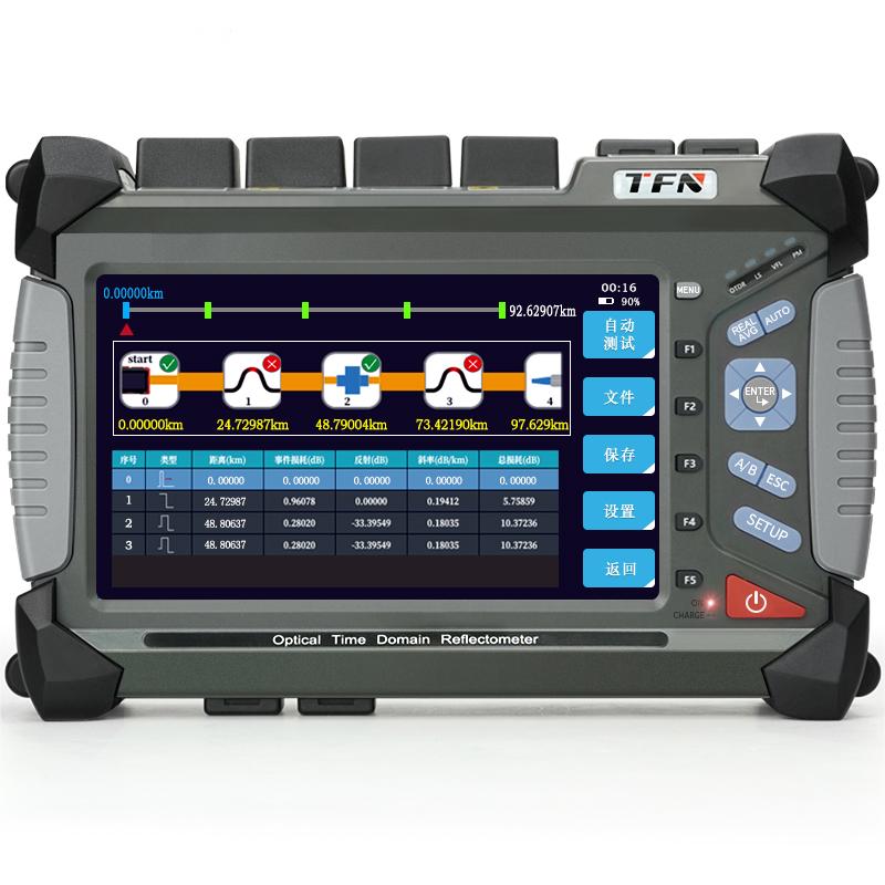
3. Non-Reflective Events
Non-reflective events are characterized by a sudden drop in the Rayleigh backscatter level and a discontinuity in the descending slope of the trace. They are usually caused by splices, macrobends, microbends, or other non-reflective losses. OTDR software reports the loss value but not reflectance. When the loss exceeds the configured threshold, the system flags a non-reflective fault.
4. Reflective Events (Possible Echoes)
Reflective events appear as sharp spikes on the trace due to abrupt refractive-index changes. These events may indicate connectors, mechanical joints, poor-quality fusion splices, or cracks. The OTDR displays both loss and reflectance for such events. Strong reflections may saturate the detector and increase the dead zone. If the reflectance or connector loss exceeds the threshold, the system reports a reflective fault.
5. Macrobend Events
Macrobend events are identified by comparing event loss at different wavelengths (e.g., 1310 nm and 1550 nm). If the longer wavelength shows greater loss, and the difference exceeds the defined limit, the OTDR confirms a macrobend. This method helps distinguish bending loss from other types of attenuation.
6. Gain Events
Gain events are uncommon in fiber-optic systems and may be caused by special connectors or joining methods. A gain event indicates an apparent increase in backscatter level at a splice, typically due to different backscattering characteristics of the two joined fibers.
7. Fiber Segments
A fiber segment refers to a portion of fiber without any events. The sum of all segments equals the total fiber length shown on the OTDR trace. OTDR software reports the loss of each fiber segment but not the reflectance. Users may calculate attenuation by dividing loss by the segment length.
8. Merged Events
Merged events occur when two or more events overlap or are too close to be individually resolved. The OTDR displays their combined loss and relevant reflectance information. The software also reports the overall reflectance and the highest reflectance among the sub-events.
9. Testing and Pass/Fail Evaluation
Pass/fail results are determined according to preset thresholds and test conditions, which should be configured based on fiber performance requirements and application scenarios. False positives or missed detections may occur. Users may choose to test all event types, only selected event types, or none. When testing all event types, each event’s loss is compared against the threshold to determine its status. This helps users evaluate the overall fiber performance and identify potential issues.
Summary
By understanding and analyzing different OTDR event types, users can more accurately locate faults within fiber-optic networks, improving the stability and reliability of communication systems.
The TFN RM7 OTDR provides clear and accurate identification of event types—including non-reflective, reflective, and macrobend events—and delivers detailed loss and reflectance information. This enables precise fault detection and rapid troubleshooting for fiber-optic communication systems.