


In power systems, the concealed nature of underground cables poses significant challenges to routine maintenance and emergency repairs. Looking beyond the power sector, the reliability of various cables—whether in railway communication, urban rail transit, or petrochemical plants—is equally critical to safety and operational efficiency. As a communication engineer, I understand the complexity of accurately and quickly locating cable faults in harsh electromagnetic environments—it is not just a technical task but also a race against time. Today, I would like to discuss the application scenarios of cable fault testers in different fields from a field engineer’s perspective, and using the FB11 cable fault tester as an example, explore how it has become an indispensable tool for cable maintenance professionals.
1. Beyond Power: Diverse Application Fields of Cable Fault Testers
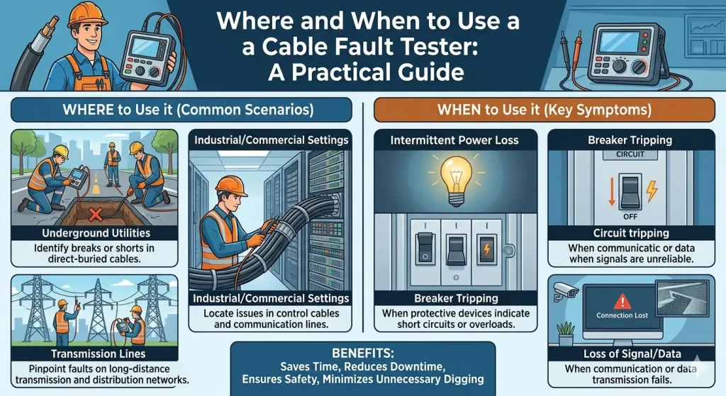
When people think of cable fault testers, the first image that often comes to mind is a utility company’s emergency crew. In reality, wherever cables exist in modern infrastructure, these testers are needed.
Railways and urban rail transit represent a typical application scenario. The signaling systems, communication optical cables, and power supply ring networks used in high-speed railways and subways are such that a failure in any critical cable can lead to a full service suspension. Along railway lines, optical cables are usually laid in communication ducts outside the railway fence. In the event of fiber breaks or increased attenuation due to water ingress in splice boxes, a cable fault tester is essential for precise location. Unlike power cables, railway communication optical cables require test equipment with higher sensitivity to identify weak reflection signals while avoiding electromagnetic interference with signaling equipment along the line.

Petrochemical plants also rely heavily on these testers. In chemical plants, control cables and instrumentation cables crisscross the facilities, often coexisting with flammable and explosive environments. In such scenarios, the intrinsic safety of the test equipment and its signal conditioning capability become top priorities. The FB11’s patented signal conditioning device offers clear advantages here—it extracts valid signals from heavily industrial environments with strong interference, ensuring reliable test results.
Municipal construction is another area where these testers are frequently used. During urban road renovation projects, the greatest fear for construction crews is accidentally cutting underground pipelines. Before breaking ground, using a cable fault tester with the direct connection method for path detection allows for accurate marking of the route and depth of each buried line, effectively preventing destructive excavation.
2. Path Detection: The Direct Connection Method for Higher Accuracy
In practical work, accurately tracing the cable path is often the first step in fault location. Many excavation sites fail to locate the fault point simply because the path detection step was not done correctly.
The FB11 comes with a coupling clamp and connecting cables, supporting two path detection modes: the induction method and the direct connection method. From a field engineer’s practical experience, the direct connection method offers the highest positioning accuracy. During operation, we connect the transmitter’s signal lead directly to the metallic sheath or one of the phase conductors of the target cable and drive a ground rod into the earth to complete the circuit. In this setup, almost all signal energy is injected into the target cable, minimizing crosstalk on adjacent cables—a common issue with the induction method.
The advantage of the direct connection method is especially evident during railway communication optical cable inspections. Communication optical cables usually contain metallic strength members or armor layers. After injecting a specific frequency signal via the direct connection method, the receiver can accurately trace the path. The FB11 receiver simultaneously provides feedback on signal strength through three indicators—digital value, bargraph fluctuation, and audible tone—allowing the path error to be controlled within centimeters, even on complex ground surfaces such as railway ballast or concrete pavement. When the signal changes abruptly at a fault point or splice, we can precisely pinpoint the abnormal location, thus avoiding blind excavation that might damage the railway substructure.
3. Fault Ranging: From Preliminary Assessment to Precise Location
Once the path is confirmed, the next step is measuring the fault distance. Whether it is an open circuit, short circuit, high-resistance leakage fault in power cables, or broken fiber or excessive attenuation in communication optical cables, the ranging step is essential.
The FB11’s digital design and software control make the ranging process highly efficient. In the field, we first perform preliminary ranging using the low-voltage pulse reflection method. The instrument sends a low-voltage pulse into the cable and calculates the fault distance based on the time difference of the reflected waveform. The FB11’s powerful data processing capability clearly displays turning points on the waveform, helping us quickly determine the fault type—whether it is an open circuit, short circuit, or impedance mismatch at a joint.
For high-resistance faults or flashover faults, low-voltage pulses cannot produce effective reflections, requiring the use of a high-voltage unit for surge flashover testing. The FB11’s high-voltage units cover a wide range from 1.5 KVA to over 300 KVA, suitable for cables at different voltage levels. For 10 kV distribution cable fault handling, a 3.0 KVA or 6.0 KVA impulse unit is sufficient to break down the high-resistance fault point; for 110 kV and above high-voltage cables, a higher power unit is required. The high-voltage impulse generates strong electromagnetic interference, and the FB11’s signal conditioning device effectively filters out noise to ensure that the captured waveform is reliable, avoiding wasted excavation caused by misinterpretation.
4. Data Management and the Engineer’s Path to Growth
From a career development perspective, each fault testing operation is a valuable accumulation of experience. The additional advantage of digital instruments like the FB11 is data storage and playback capability. After field tests, we can export the waveform data for writing fault analysis reports or use it as training material for newly joined engineers.
For maintenance teams in sectors such as railway communications and petrochemical power, building a cable health archive is becoming a trend. Recording each test’s data into a backend system and managing it alongside GIS geographic information provides a scientific basis for preventive maintenance and condition-based maintenance. A good cable fault tester must not only solve problems in the field but also serve as a fundamental tool for data collection and management.
الخاتمة
Whether for power cables, railway communication optical cables, or control cables in petrochemical plants, the cable fault tester is a critical piece of equipment for ensuring reliable cable operation. The FB11 cable fault tester integrates digital control, multi‑dimensional signal feedback, dual path detection modes (direct connection and induction) , and a wide‑range high‑voltage unit configuration, effectively addressing the various pain points engineers encounter in the field.
From a communication engineer’s perspective, the seamless collaboration between the operator and the instrument is the essence of efficient fault handling. Choosing a stable, intelligent, and user‑friendly أجهزة اختبار أعطال الكابلات like the FB11 not only improves work efficiency but also gives us more confidence and capability when facing each cable fault challenge.
Contact TFN support team:
البريد الإلكتروني: info@tfngj.com
واتساب: +86-18765219251
أو يمكنك leave message here