


In the maintenance of communication and power infrastructure, the cable fault tester serves as a core tool for ensuring line stability. With the increasing complexity of distribution networks, especially the widespread application of medium and low-voltage cables below 35KV, rapidly and accurately locating faults has become a primary technical challenge for field engineers. This article will delve into the application principles of electromagnetic induction technology in cable fault location from the perspective of a communication engineer. It will also explore the technical advantages and practical value of the TFN FB11 Cable Fault Tester in complex field environments, based on its engineering performance.
I. Electromagnetic Induction: From Principle to Engineering Implementation
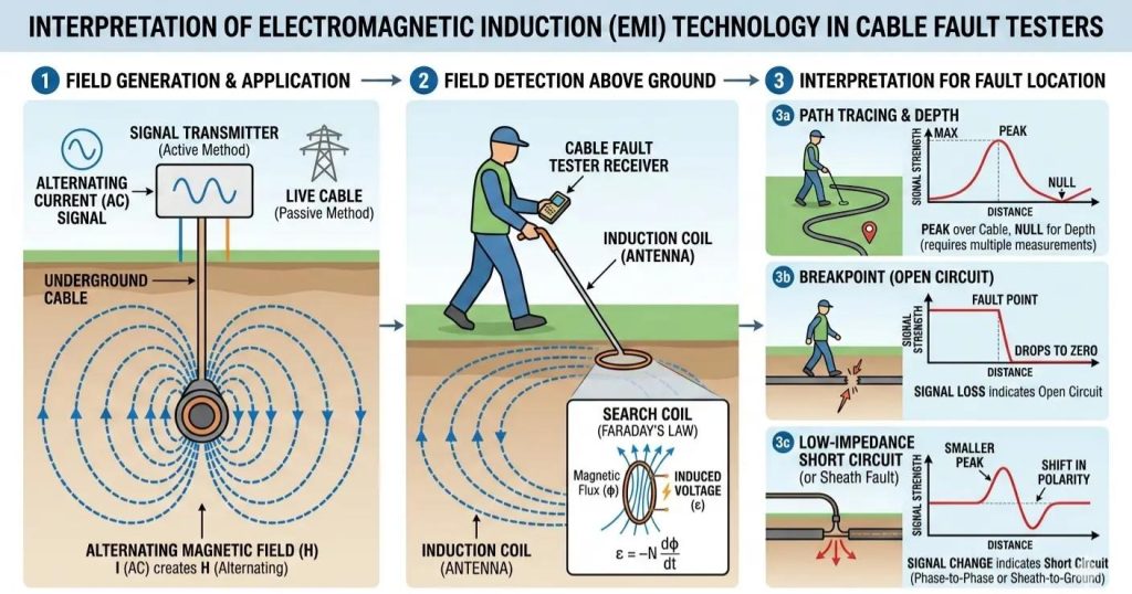
The core logic of applying electromagnetic induction technology to cable fault detection is not complicated: by injecting a signal of a specific frequency into the faulty cable, an electromagnetic field is excited. A receiving coil then senses the field strength distribution, allowing the fault point’s location to be determined inversely. [1] This principle was applied to underground pipeline detection as early as the mid-20th century, but achieving high-precision, anti-interference engineering implementation has been a more recent breakthrough.
From a signal processing perspective, electromagnetic induction methods can be categorized into passive and active types. Passive methods rely on the cable’s own power frequency signal or its harmonic components, making them suitable for live identification scenarios. Active methods, on the other hand, involve an transmitter injecting a specific frequency signal, which is ideal for fine detection in a de-energized state.
In practical applications, the difficulty of active electromagnetic induction technology lies in the fact that the signal is easily affected by factors such as changes in soil dielectric constant, interference from adjacent metal pipelines, and variations in cable burial depth. Therefore, modern cable fault testers must possess capabilities such as multi-frequency adjustability, adaptive gain control, and digital signal processing to achieve stable interpretation in complex environments.
II. From Signal Excitation to Intelligent Interpretation: How Does the FB11 Achieve Precise Location?
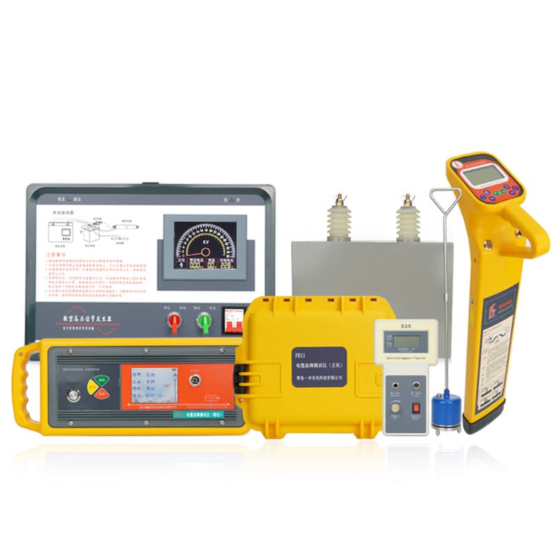
Taking the TFN FB11 Cable Fault Tester as an example, its electromagnetic induction functionality is primarily embodied in the “Path Finding and Identification Unit”—the cable path detector module. This module integrates a transmitter and a receiver, supports multiple operating modes, and can simultaneously perform path tracking, depth measurement, and fault point location.
From a communication engineer’s perspective, the FB11’s design logic clearly addresses three major pain points in field operations:
1. Multi-frequency Adjustability and Impedance Adaptation
The FB11 transmitter supports switching between four frequency bands: Low, Medium, High, and Radio Frequency, with a matching load range covering 1Ω to 25500Ω. This means that whether it’s a low-resistance short circuit fault or a high-resistance open circuit fault, an appropriate signal injection method can be found. Particularly in scenarios involving metallic dead shorts, where traditional high-voltage impulse methods often fail, electromagnetic induction can still establish an effective signal path through impedance matching and frequency optimization.
2. Engineering Trade-off Between Peak and Null Methods
The receiver offers both Peak and Null methods. The Peak method is suitable for scenarios with strong signals and clear paths, determining the cable route by identifying the signal maximum point. The Null method has an advantage in environments with high interference, improving location accuracy by utilizing the signal null point. The FB11 receiver supports both graphical bar graphs and numerical displays (0-999 range), with a gain adjustment range of 0-100dB, allowing engineers to flexibly adjust sensitivity based on on-site noise levels.
3. Direct Depth Reading and Current Indication
Depth measurement is another critical indicator of electromagnetic induction technology. The FB11 supports one-key direct depth reading (within 250cm) and the 80% method for depth measurement (within 600cm). It also displays the effective current value (in mA) of the cable under test in real-time. This feature is particularly important in urban environments with dense cross-interference from pipelines, effectively preventing the misidentification of adjacent cables as the fault target.
III. From Ranging to Pinpointing: How Does an Integrated System Work Together?
Electromagnetic induction technology does not operate in isolation. In the overall architecture of the FB11, electromagnetic induction is primarily responsible for path identification and coarse location, while precise pinpointing is accomplished by the Fault Pinpointing Unit in coordination with the High-Voltage Signal Generator.
A typical operational workflow is as follows:
1. Initial Ranging: Use the ranging host unit with low-voltage pulse or high-voltage flashover methods to preliminarily determine the fault distance range.
2. Path Tracing: Activate the electromagnetic induction mode to trace signal variations along the cable path and mark areas of anomaly.
3. High-Voltage Impulse Pinpointing: Apply high-voltage impulses in the suspected area to excite discharge at the fault point.
4. Acoustic-Magnetic Synchronous Pinpointing: The pinpointing unit simultaneously receives the sound waves and electromagnetic waves generated by the discharge, locating the fault point with an accuracy of 0.1 meters.
The engineering value of this process lies in the fact that electromagnetic induction technology significantly narrows down the manual inspection range, avoiding unnecessary excavation. The acoustic-magnetic synchronous method compensates for the shortcomings of electromagnetic methods, where signal attenuation can be too rapid in high-resistance faults. Through this synergy, the FB11 can cover almost all types of faults in cables below 35KV, including open circuits, short circuits, dead grounds, and high-resistance leaks.
IV. Techological Evolution and Engineering Insights
From a technological development perspective, electromagnetic induction methods are evolving towards multi-frequency integration, intelligent interpretation, and real-time visualization. The digital design, software control, and color LCD interface adopted by the FB11 essentially represent a comprehensive upgrade from traditional analog instruments. The underlying logic is to lower the barrier to on-site interpretation through digitization, thereby enhancing test reliability in complex environments.
For communication engineers, understanding the physical essence of electromagnetic induction technology is far more important than memorizing operational steps. The propagation path of signals underground, the impact of frequency on penetration depth, the directional selectivity of the receiving coil—these fundamental principles determine the accuracy and repeatability of test results.
الخاتمة
The essence of cable fault testing is a battle in an “unseen battlefield.” Electromagnetic induction technology, with its non-contact, quantifiable, and highly adaptable characteristics, has become the primary equipment in this battlefield. As a representative of domestic instruments, the TFN FB11 makes engineering attempts in areas such as path identification, depth measurement, and anti-interference capability, essentially meeting the routine operation and maintenance needs for cables below 35KV.
In the future, with the introduction of the Internet of Things (IoT) and AI-assisted diagnostic technologies, electromagnetic induction methods may deeply integrate with big data models to achieve fault prediction and proactive maintenance. However, for front-line engineers, understanding the technical principles and mastering the equipment logic remains the foundation for ensuring the stable operation of power grids.
إذا كنت مهتمًا ب TFN FB11 Cable Fault Testing System, ، مرحبًا بك للتواصل مع فريق دعم TFN:
البريد الإلكتروني: info@tfngj.com
واتساب: +86-18765219251
أو يمكنك leave messages Here
الأسئلة الشائعة
In cable maintenance, electromagnetic induction is primarily used for path tracing and cable identification. By injecting a specific frequency signal into the faulty line, the tester creates an electromagnetic field that can be detected from the surface. This allows engineers to map the exact route and burial depth of the cable, which is a critical “coarse location” step before precise pinpointing begins.
Different field environments require different signal characteristics. Low frequencies have stronger penetration and are ideal for long-distance tracing, while higher frequencies provide better sensitivity for detecting subtle signal changes in complex environments. The FB11 supports four frequency bands and a wide impedance matching range (1Ω to 25,500Ω), ensuring a stable signal regardless of whether the fault is a low-resistance short or a high-resistance leak.
إن Peak Method identifies the cable route by locating the signal maximum; it is intuitive and best for general path tracking. The Null Method uses the signal’s minimum (zero) point to determine the center of the cable. While it requires more precision, the Null Method is superior in high-interference areas (such as urban centers with many adjacent pipes) because it provides a sharper, more accurate location of the cable’s axis.
Generally, no. Electromagnetic induction is excellent for identifying the path and narrowing down the search area, but high-resistance faults often cause rapid signal attenuation. To achieve pinpointing accuracy (within 0.1 meters), the FB11 uses a synergistic approach: the induction unit identifies the path, and the Acoustic-Magnetic Synchronous unit detects the physical discharge at the fault point created by a high-voltage generator.
The TFN FB11 solves this through real-time current (mA) display و direct depth reading. Since the transmitter signal is only injected into the target cable, that cable will exhibit a unique current signature. By monitoring the effective current value and depth simultaneously, engineers can distinguish the target cable from nearby metallic structures that might be picking up “ghost” signals.