


Electromagnetic induction is the physical phenomenon in which a changing magnetic field induces an electric current in a nearby conductor. Underground pipe locators transform this fundamental principle into a controlled signal transmission and reception system for detecting buried metallic pipelines and cables.
In practical underground pipeline detection, a transmitter generates an alternating current (AC) signal at a selected frequency and applies it to the target pipeline using one of three methods: direct connection, coupling, or induction. Once energized, the pipeline carries an alternating current that produces a surrounding electromagnetic field at the same frequency.
A pipe locator receiver equipped with precision antennas senses this magnetic field, converts it into an electrical signal, and processes it through digital filtering, gain control, and phase analysis. The processed data is then displayed visually and audibly, allowing the operator to accurately determine pipeline position, direction, and depth. The point of maximum signal response is located directly above the pipeline, forming the basis for precise route tracing.
Signal Application Methods in Underground Pipeline Detection
Direct Connection Method: High-Accuracy Pipeline Locating
The direct connection method is the most accurate signal application technique for underground pipe locators. It is primarily used for de-energized metallic pipelines or cables. In this method, the transmitter applies a signal directly to the target line using test leads:
- The red lead connects to the target conductor or pipeline
- The black lead connects to an independent ground rod
This configuration forms a closed signal loop, allowing the AC signal to travel efficiently along the pipeline. Because signal loss is minimal, the direct connection method offers long tracing distances, strong signal stability, and superior locating accuracy. When site conditions permit, it is the preferred method for professional underground pipe locator operation.
Coupling Method: Safe Detection of Live Cables
The coupling method applies the signal indirectly using a coupling clamp placed around the target cable. No electrical contact is required, making this method ideal for live cable detection where safety is critical.
Signal coupling efficiency depends on frequency. Higher frequencies generally provide better coupling performance, particularly on energized cables. For route tracing and cable identification in active electrical environments, the coupling method delivers stable and reliable results without interrupting service.
Induction Method: Non-Contact Detection of Unknown Pipelines
The induction method requires no physical connection to the pipeline. Instead, the transmitter radiates a high-frequency electromagnetic signal (commonly 82 kHz or 133 kHz) into the ground through its internal antenna.
When this signal encounters an underground metallic pipeline, it induces a secondary current within the conductor. This current generates its own electromagnetic field, which is detected by the receiver. The induction method is especially effective for preliminary surveys, blind testing, and locating unknown pipelines where access points are unavailable.
Receiver Signal Processing and Locating Modes
Modern underground pipe locators support multiple receiver modes to adapt to different site conditions and interference levels.
Peak Mode
In peak mode, the signal strength reaches its maximum directly above the pipeline. This mode is widely used for route tracing and depth measurement due to its simplicity and reliability.
Trough Mode
Trough mode displays the weakest signal directly above the pipeline, with stronger signals appearing on either side. This mode is particularly useful for verifying pipeline position in congested underground environments where signal interference or coupling distortion is present.
Wide Peak Arrow Mode
Wide peak arrow mode combines directional arrows with signal strength indication, allowing operators to visualize pipeline direction and positional deviation in real time. This mode significantly improves locating efficiency, especially during long-distance tracing.
The receiver continuously displays key parameters such as signal strength, current magnitude, depth, and phase information. Integrated audio feedback further reduces operator fatigue and improves accuracy during extended field operations. Phase and current direction analysis help distinguish target signals from crosstalk, which is essential in areas with multiple parallel pipelines.
Practical Applications of Underground Pipe Locator Technology
Underground Pipeline Route Tracing
Regardless of the signal application method used, route tracing follows a consistent workflow:
- Apply the signal to the target pipeline
- Search for the signal using the receiver
- Track the peak or trough signal path
- Mark the pipeline route accurately
Proper gain adjustment and baseline signal calibration are critical to avoid false readings caused by environmental electromagnetic interference.
Pipeline Depth Measurement
After the pipeline route is established, the underground pipe locator can calculate burial depth automatically. For verification, the 80% method is commonly used:
- Measure signal strength directly above the pipeline
- Move laterally until the signal drops to 80% of the peak value
- Measure the horizontal distance between these two points
This distance corresponds to the pipeline burial depth, providing a reliable cross-check of the displayed measurement.
Cable Identification and Phase Verification
In environments with multiple underground cables, accurate cable identification is essential to prevent accidental damage. By combining a coupling clamp with phase and current direction analysis, operators can positively identify the target cable.
Signal calibration and phase comparison ensure safe excavation and maintenance operations, particularly in power and telecommunications networks.
Blind Testing for Unknown Underground Pipelines
When pipeline drawings are missing or outdated, blind testing techniques are used. By coordinating transmitter and receiver positioning through systematic scanning methods such as point testing or face-to-face detection, underground metallic objects can be identified and mapped efficiently.
Blind testing is widely applied during pre-construction surveys and infrastructure assessment projects.
Advantages and Limitations of Electromagnetic Induction Pipe Locators
Electromagnetic induction-based underground pipe locators offer several key advantages:
- High locating accuracy for metallic pipelines and cables
- Fast, non-destructive detection
- Strong adaptability to live and de-energized lines
- Efficient operation in urban environments
However, performance can be affected by pipeline material, burial depth, soil resistivity, and surrounding electromagnetic interference. Non-metallic pipelines require complementary detection technologies such as ground-penetrating radar (GPR), and complex installations benefit from combining field measurements with existing infrastructure records.
Conclusion
Electromagnetic induction forms the technical foundation of modern underground pipeline detection. By transforming electromagnetic field variations into intuitive locating data, underground pipe locators enable precise route tracing, depth measurement, and cable identification without excavation.
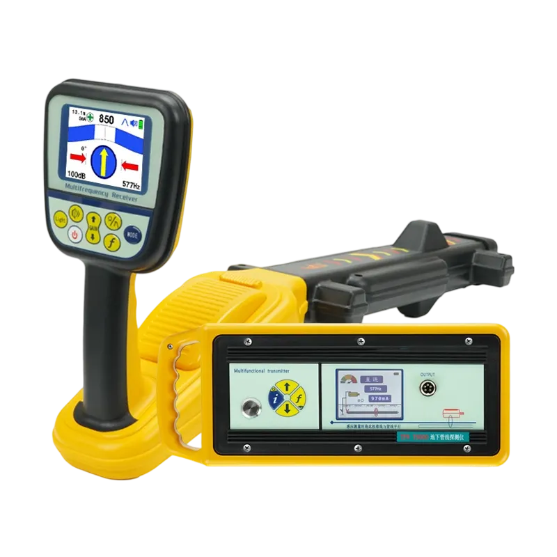
The T6000 Underground Pipe Locator integrates advanced transmitter and receiver technology to deliver reliable performance across municipal construction, power utilities, telecommunications, and oil and gas applications. As urban infrastructure continues to grow in complexity, electromagnetic induction-based pipe locators will remain essential tools for safe, efficient, and intelligent underground asset management.