


At the heart of every robust optical fiber network lies a critical, nearly invisible process: fusion splicing. This technique permanently joins two optical fibers end-to-end using heat. Its primary goal is to create a continuous optical path that minimizes signal loss (attenuation) and reflection, ensuring light pulses travel seamlessly across vast distances. Unlike mechanical connectors, a fusion splice forms a solid, durable joint with superior long-term reliability and performance, making it the undisputed standard for permanent installations in telecommunications, data centers, and cable television networks.
The core challenge is achieving a near-perfect merger. The typical core of a single-mode fiber is only 9 microns in diameter. Precise alignment and controlled fusion are paramount to prevent light from scattering or escaping at the splice point. This is where the advanced technology of the modern fusion splicer comes into play, mastering the interplay of optics, precision mechanics, and thermal engineering.

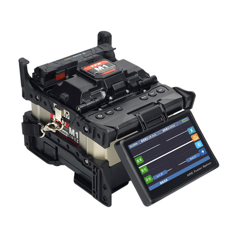
Core Components of a Fusion Splicer: The Engine of Precision
To understand the principle, one must first understand the machine. A fusion splicer is a sophisticated system built around several key subsystems:
- The Alignment System: This is the “eyes and hands” of the splicer. It consists of high-magnification lenses, cameras or optical sensors, and precision micro-motors. Its job is to view the fiber ends from two perpendicular angles (X and Y axes) and maneuver them into perfect coaxial alignment.
- The Fusion System: This is the “heart.” It comprises a pair of electrodes that generate a high-voltage electric arc. This arc creates the intense, localized heat (around 1700-2000°C) necessary to melt the silica glass of the fiber ends.
- The Control and Processing Unit: This is the “brain.” It processes the fiber images, runs alignment algorithms, controls the motors and arc discharge with precise timing, and evaluates the quality of the finished splice.
Step-by-Step: The Arc Fusion Splicing Procedure
The process is a marvel of automation and precision, typically completed in under two minutes.
Step 1: Fiber Preparation
The process begins with proper preparation. The protective coating is stripped from the fiber ends, and the bare glass is meticulously cleaned with high-purity alcohol. Then, a fiber cleaver scores and breaks the fiber to create a perfectly flat, mirror-smooth end face. The quality of this cleave is fundamental; an angle greater than a fraction of a degree can significantly increase splice loss.
Step 2: Fiber Loading and Automatic Alignment
The prepared fibers are placed into the splicer’s guide grooves. Upon initiation, the machine performs an automatic sequence:
1. Cleaning Discharge: A brief, low-power arc cleans any microscopic contaminants from the fiber end faces.
2. Fiber Imaging and Core Detection: The system captures images, uses pattern recognition to locate the fiber cladding boundaries, and in advanced models, directly detects the core’s position.
3. Precision Alignment: The micro-motors adjust the fibers’ positions in X, Y, and Z axes. Modern splicers perform core alignment, directly aligning the light-guiding cores for the lowest possible loss, especially critical for single-mode fibers.
Step 3: The Arc Fusion Process
This is the critical phase where physics takes over. With fibers perfectly aligned and separated by a microscopic gap, the splicer initiates a controlled arc discharge.
- Prefusion: A short, low-intensity arc preheats the fiber ends, rounding any sharp edges and preparing the glass.
- Main Fusion and Push: The main arc is applied, rapidly melting the fiber ends. Simultaneously, the precision motors push the fibers together at a controlled speed. The surface tension of the molten glass pulls the ends together, forming a continuous, smooth joint. The splicer’s software meticulously controls arc intensity and duration based on fiber type and environmental conditions.
Step 4: Splice Protection and Evaluation
Once fused and cooled, the splice is incredibly fragile without protection. The machine moves the splice point into a heat shrink splice protector. A built-in heating oven shrinks the protector around the joint, providing mechanical strength and environmental sealing. Finally, the splicer estimates the splice loss (in decibels, dB) by analyzing the light transmitted through or scattered from the splice point. High-quality splices routinely achieve losses below 0.05 dB.
Key Factors Influencing Splice Quality and Performance
From an engineering perspective, several interlinked factors determine success:
- Fiber Core Alignment Accuracy: This is the single greatest factor for low loss. Sub-micron accuracy is required.
- Arc Stability and Control: Consistent, clean discharge is vital. Electrode wear, humidity, and altitude affect the arc and require system calibration.
- End-Face Quality (Cleave Angle): A bad cleave cannot be corrected by splicing. It causes axial misalignment and increased loss.
- Environmental Contamination: Dust or moisture on the fiber or within the splicer’s V-grooves disrupts alignment and fusion.
- Software Algorithms: The intelligence behind auto-focusing, core detection, arc calibration, and loss estimation is what transforms hardware into a reliable tool.
Conclusion: The Invisible Foundation of Connectivity
Arc fusion splicing is more than just melting glass; it is a repeatable, high-precision manufacturing process performed in the field. It transforms individual fiber segments into a continuous, low-loss optical waveguide. By mastering the principles of optical alignment, thermal dynamics, and automated control, modern fusion splicers build the nearly perfect, invisible junctions that form the reliable backbone of our global digital infrastructure. As networks evolve towards denser fibers and stricter loss budgets, the precision and intelligence of these tools will only become more critical.